

Method for making head of golf club and beating surface plate
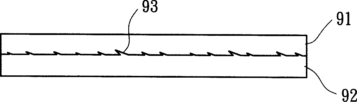
A technology for golf club heads and manufacturing methods, which is applied to golf balls, golf clubs, rackets, etc., and can solve problems such as increased cost, impact on ball hitting performance, and uneven joint surface 93
- Summary
- Abstract
- Description
- Claims
- Application Information
AI Technical Summary
Problems solved by technology
Method used
Image

Examples
Embodiment Construction
[0029] In order to make the purpose, technical features, and advantages of the present invention clearer, preferred embodiments will be specifically cited below, and detailed descriptions will be given below in conjunction with the accompanying drawings.
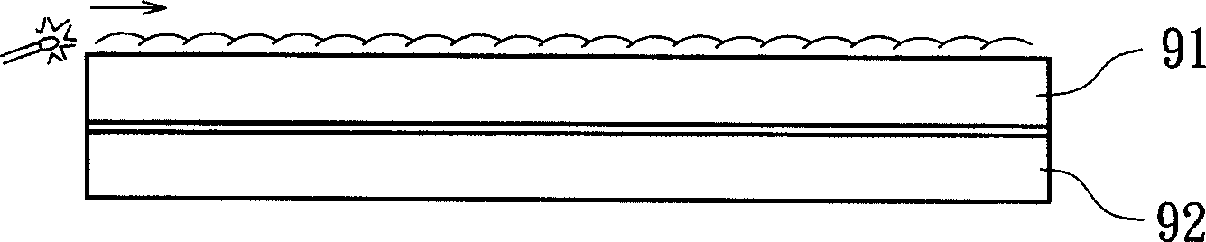
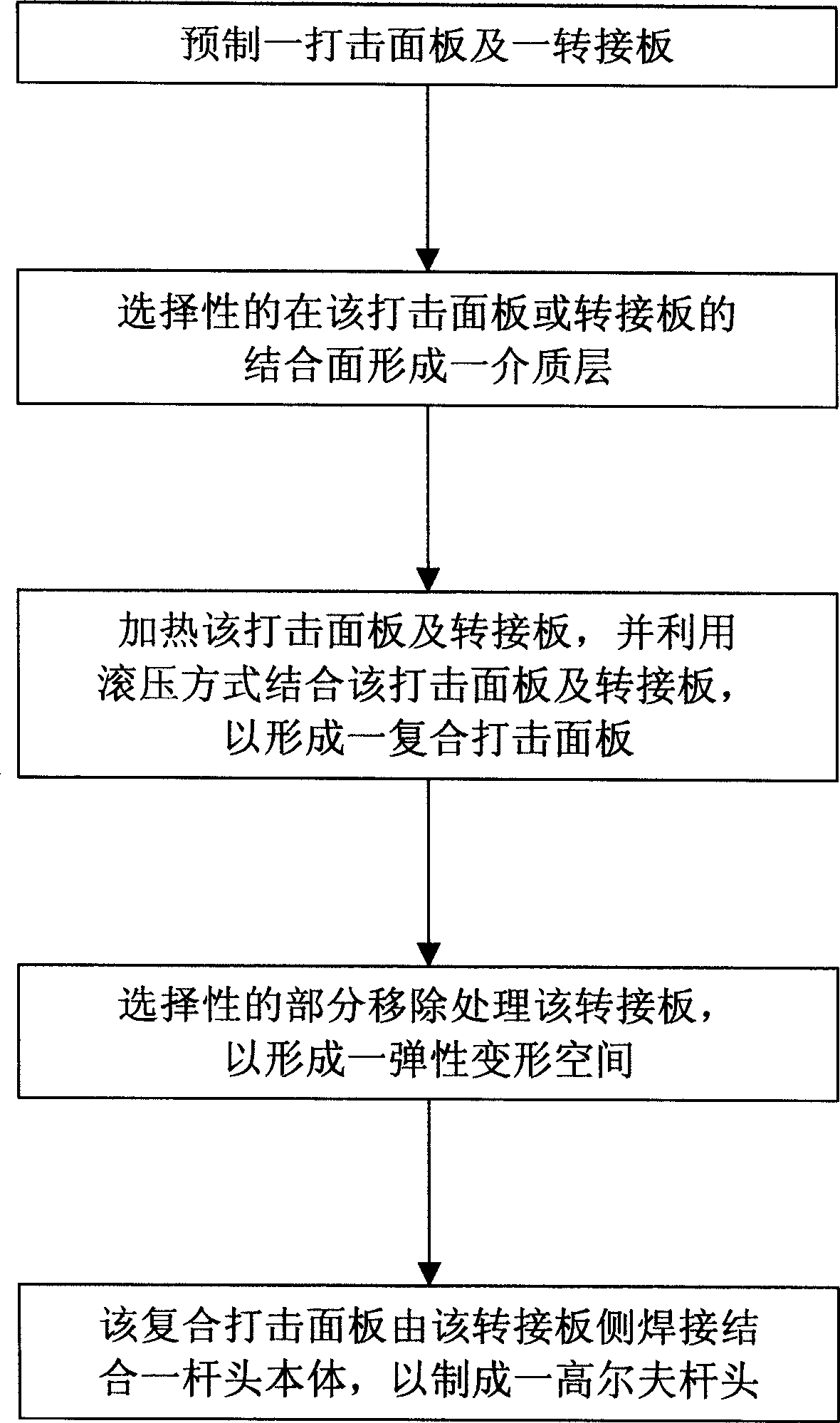
[0030] Please refer to Figure 3-9 As shown, the manufacturing method of the golf club head and the striking panel in the first embodiment of the present invention includes the steps of: prefabricating a striking panel 10 and an adapter plate 20; A dielectric layer 30 is formed on the joint surface; the striking panel 10 and the adapter plate 20 are heated, and the striking panel 10 and the adapter plate 20 are combined by rolling to form a composite striking panel 40; selective partial removal process The adapter plate 20 is used to form an elastic deformation space 21 ; and the composite striking panel 40 is welded from the adapter plate 20 to a club head body 50 to form a golf club head.
[0031] please refer again ima...
PUM
 Abstract
Description
Claims
Application Information