Main transmission device of rolling machine

A main drive and plate rolling machine technology, applied in the field of plate rolling machines, can solve the problems of large universal couplings, difficult processing, and high price, and achieve the effects of ensuring production safety, avoiding easy damage, and reducing manufacturing costs

Inactive Publication Date: 2007-01-31
王小建
View PDF0 Cites 5 Cited by
  • Summary
  • Abstract
  • Description
  • Claims
  • Application Information

AI Technical Summary

Problems solved by technology

In this case, the universal coupling is relatively large, and the torque it carries is relatively large, and it is easy to break during work. Because the large universal coupling is not easy to process, it is expensive, which makes the cost of the main transmission device relatively high.

Method used


Image

  • Main transmission device of rolling machine
  • Main transmission device of rolling machine

Examples


Embodiment Construction

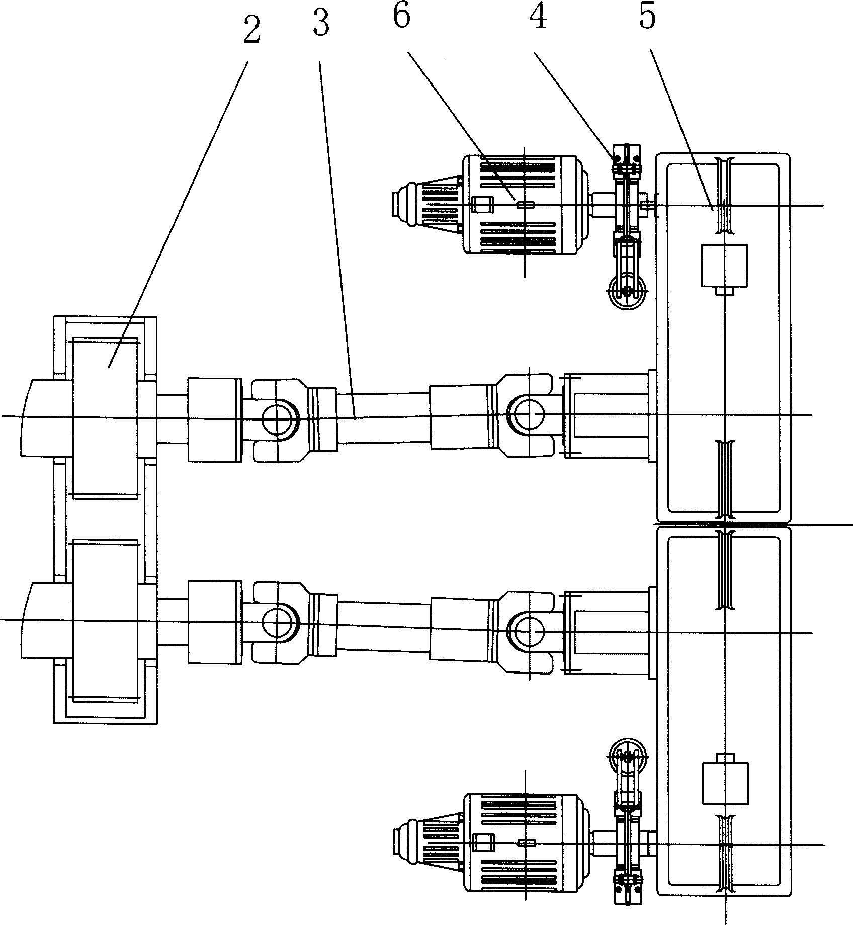
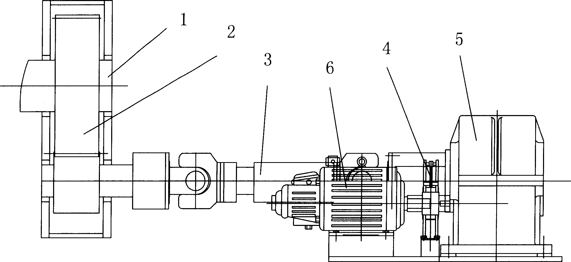
[0009] The present invention is further described below in conjunction with embodiment. Such as figure 1 with figure 2 As shown, the present invention discloses a main transmission device of a plate rolling machine, including a lower roll 1, a reduction device 2, a universal coupling 3, a brake 4, a reducer 5, and a motor 6. The lower roll 1 shaft The end is equipped with a one-stage or multi-stage deceleration device 2, and then connected to the decelerator 5 connected to the motor 6. In this way, the universal coupling is not needed, which can greatly reduce the cost, and also avoid the problem that the coupling is easily damaged. Ensure production safety.

[0010] A universal coupling 3 can be installed between the speed reducer 2 mounted on the shaft end of the lower roller and the speed reducer 5 connected to the motor 6, or it can be installed directly between the speed reducer mounted on the shaft end of the lower roller and the motor. Universal coupling is arrange...


PUM


Abstract

A master drive mechanism for sheet coiling machine is composed of a lower roller, speed reducer A for said lower roller, motor, speed reducer B for said motor, brake and universal coupling installed between speed reducer A and the speed reducer B or motor.

Description

technical field [0001] The present invention relates to a plate bending machine, and is particularly related to its main transmission device. Background technique [0002] The main transmission device of the existing plate rolling machine is generally connected to the reducer by the motor, and then connected to the lower roller through a universal coupling. In this case, the use of the universal joint is relatively large, and the load torque is relatively large, and it is easy to break during work. Since the large universal joint is not easy to process, it is expensive, which makes the cost of the main transmission device relatively high. Contents of the invention [0003] In order to solve the deficiencies of the prior art, the present invention provides a main transmission device of a plate bending machine, which may not use or use a smaller universal coupling to reduce costs and reduce the possibility of being damaged. [0004] In order to achieve the above object, the...

Claims


Application Information

Patent Timeline
Patent Type & Authority Applications(China)
IPC IPC(8): B21D5/00B21D5/06B21D5/14
Inventor 王小建
Owner 王小建
Why Eureka
Try Eureka