Lock cabinet system
A technology for lockers and mobile communication terminals, which is applied in combination locks, building locks, locks, etc. It can solve the problems of not being able to confirm the arrival of the goods, not being able to open the lock, and inconvenience, so as to avoid the danger of loss and theft Effect
- Summary
- Abstract
- Description
- Claims
- Application Information
AI Technical Summary
Problems solved by technology
Method used
Image
Examples
Embodiment 1
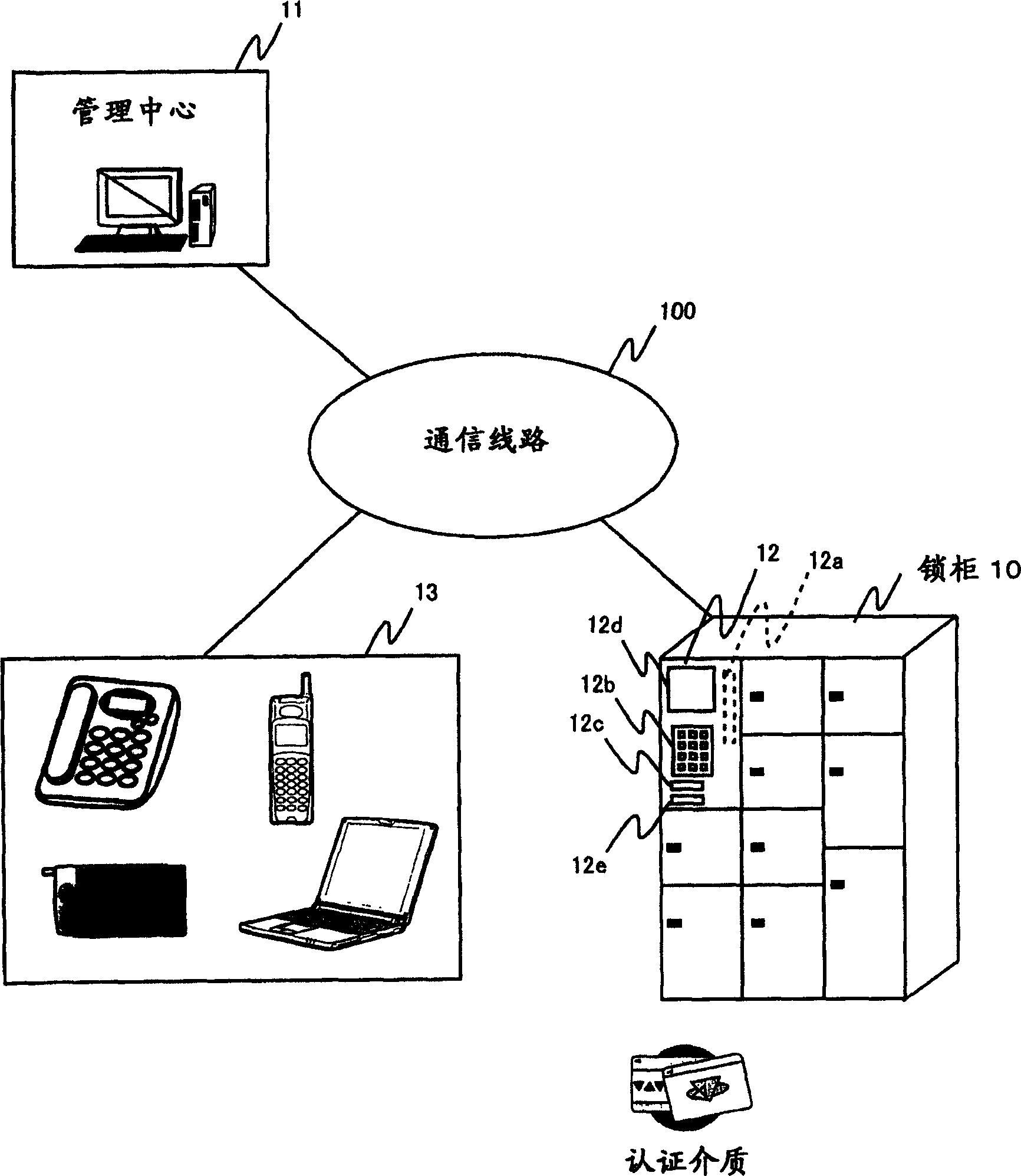
[0050] figure 1 It is a block diagram showing a schematic configuration of a locker system as Embodiment 1 of the present invention.
[0051] exist figure 1 Among them, the locker system as Embodiment 1 of the present invention is constituted by connecting the locker 10 and the management center 11 managed by the management company which manages the use status and storage information of the locker 10 through the communication line 100 . The management center 11 is constituted by a PC terminal, and monitors and manages various conditions in the locker 10 through an additional system management server and functions of various operation monitoring and operation control in the entire locker system.
[0052] The locker 10 is provided with a communication function for communicating with the management center 11 via the communication line 100, and also includes storage boxes of various sizes such as large, medium and small. In addition, a control box 12 is equipped in a part of the...
Embodiment 2
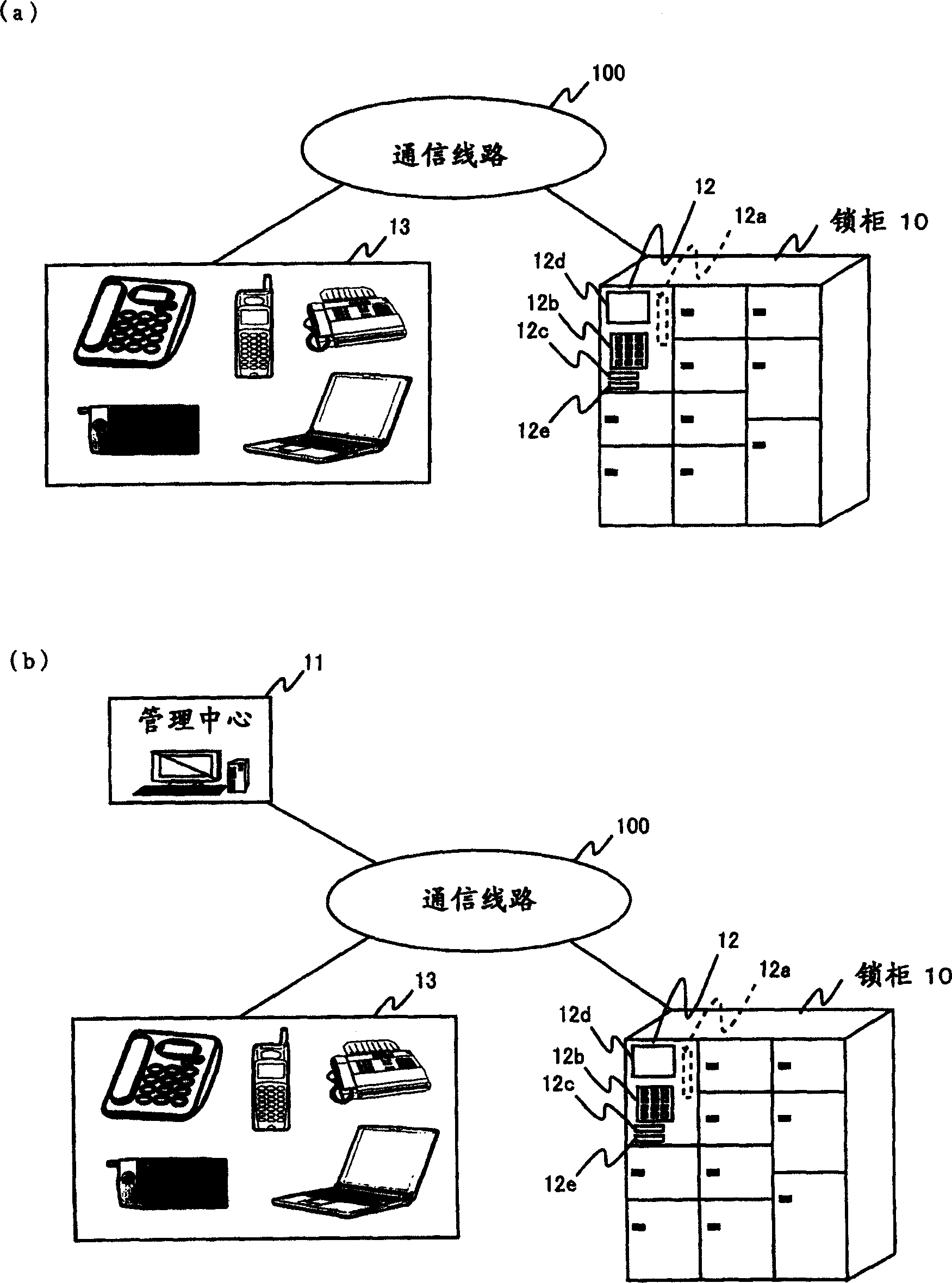
[0069] figure 2 It is a block diagram showing a schematic configuration of a locker system as a second embodiment of the present invention.
[0070] exist figure 2 In (a), as the first configuration of the locker system according to Embodiment 2 of the present invention, it is shown that the locker 10 is connected through the communication line 100, and the contact of a fixed telephone, a mobile phone, a facsimile device, etc. as a contact destination designated by the user in advance Use the structure of terminal 13.
[0071] Hereinafter, an outline of the operation of the first configuration will be described.
[0072] First of all, if the house sender makes the locker 10 recognize that he has the use authority by letting the card reader 12c read the authentication medium given in advance by the management company of the locker or the service provider company, he will input the destination address through the operation key 12b. The address information and the like are u...
Embodiment 3
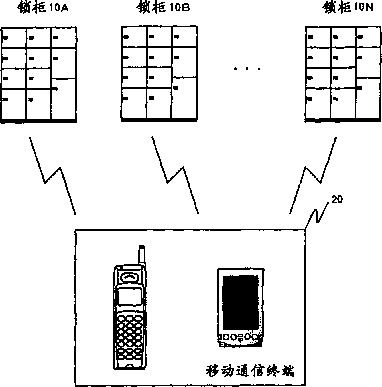
[0086] image 3 It is a block diagram showing a schematic configuration of a locker system according to Embodiment 3 of the present invention. exist image 3 Among them, the locker system as the third embodiment of the present invention is constituted by a plurality of lockers 10A to 10N, mobile communication terminals 20 such as mobile phones and PDAs (portable terminals).
[0087] Each of the lockers 10A to 10N has a control function for controlling the locking / unlocking of the locker door, and as a device for directly exchanging data with the mobile communication terminal 20, infrared communication and Bluetooth (Bluetooth) communication are installed. etc. communication functions and / or scanning functions for data acquisition by barcode information.
[0088] The mobile communication terminal 20 is a communication terminal (a mobile phone, a PDA having a communication function, etc.) owned by the person wishing to use the locker. Furthermore, the mobile communication ter...
PUM
 Abstract
Description
Claims
Application Information
 - R&D
- Intellectual Property
- Life Sciences
- Materials
- Tech Scout
- Unparalleled Data Quality
- Higher Quality Content
- 60% Fewer Hallucinations
Browse by: Latest US Patents, China's latest patents, Technical Efficacy Thesaurus, Application Domain, Technology Topic, Popular Technical Reports.
© 2025 PatSnap. All rights reserved.Legal|Privacy policy|Modern Slavery Act Transparency Statement|Sitemap|About US| Contact US: help@patsnap.com


