
Optical time domain reflectometer, and optical fiber measuring method and optical fiber measuring system using the same

a technology of optical time domain and reflectometer, which is applied in the direction of transmission monitoring, nuclear elements, nuclear engineering, etc., can solve the problems of inflexible response to the situation on-site by procedures such as “sequential measurement”, the relevance between the file name set in advance and the actual measurement of optical fiber disappearing, and the troublesome work of report generation. to achieve the effect of eliminating the troublesomeness of report generation and facilitating the identification of measured data

Inactive Publication Date: 2009-11-17
ANRITSU CORP
View PDF12 Cites 14 Cited by
  • Summary
  • Abstract
  • Description
  • Claims
  • Application Information

AI Technical Summary

Benefits of technology

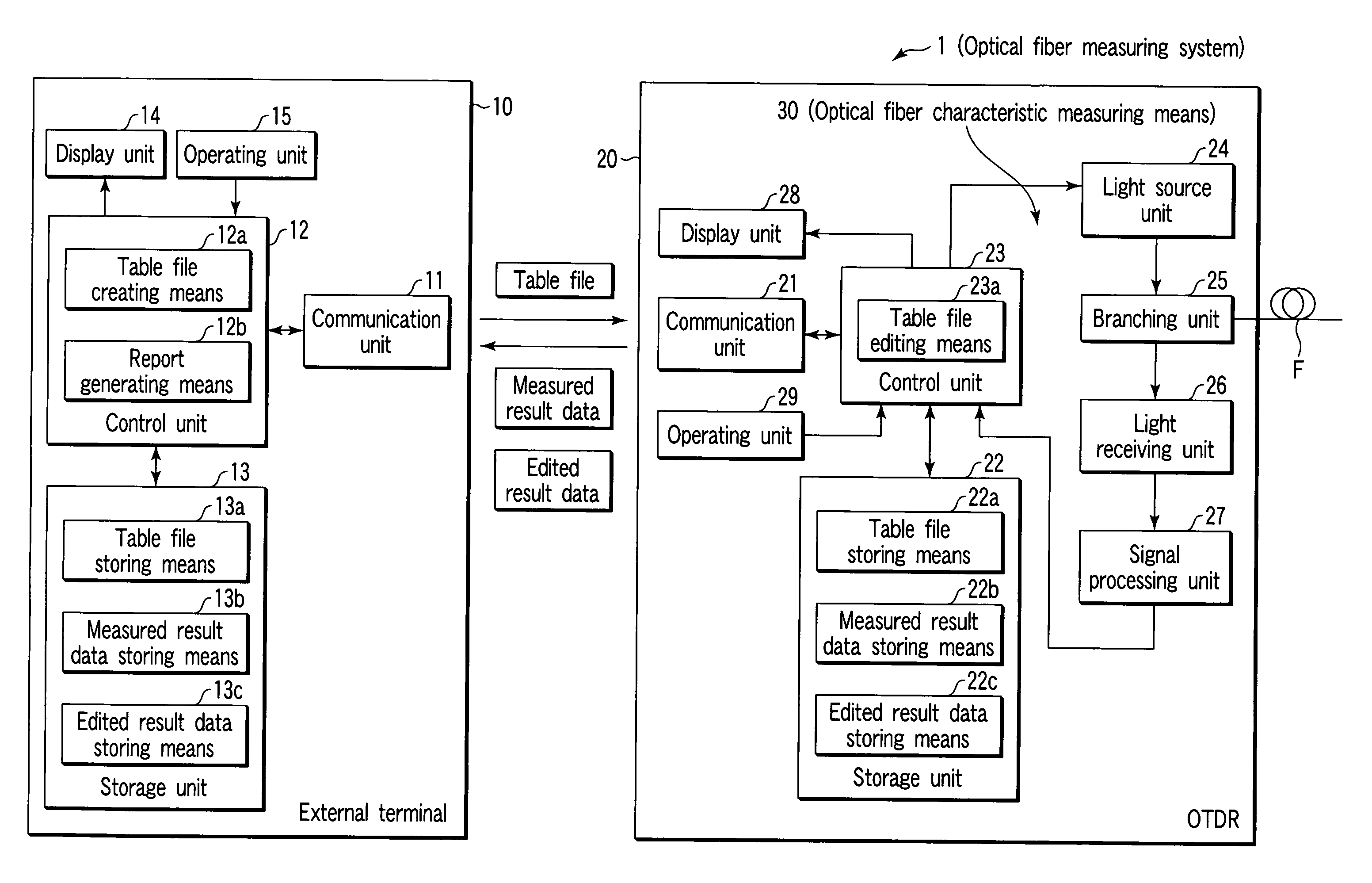
[0026]In order to solve the problems in the conventional technology as described above, an object of the present invention is, in particular, to provide an optical time domain reflectometer using a technique by which it is possible to reduce the load imposed on a cable laying / maintenance construction by simplifying an operation status according to laying / characteristic evaluations of a multicore optical fiber, and to provide an optical fiber measuring method and an optical fiber measuring system which use the same.
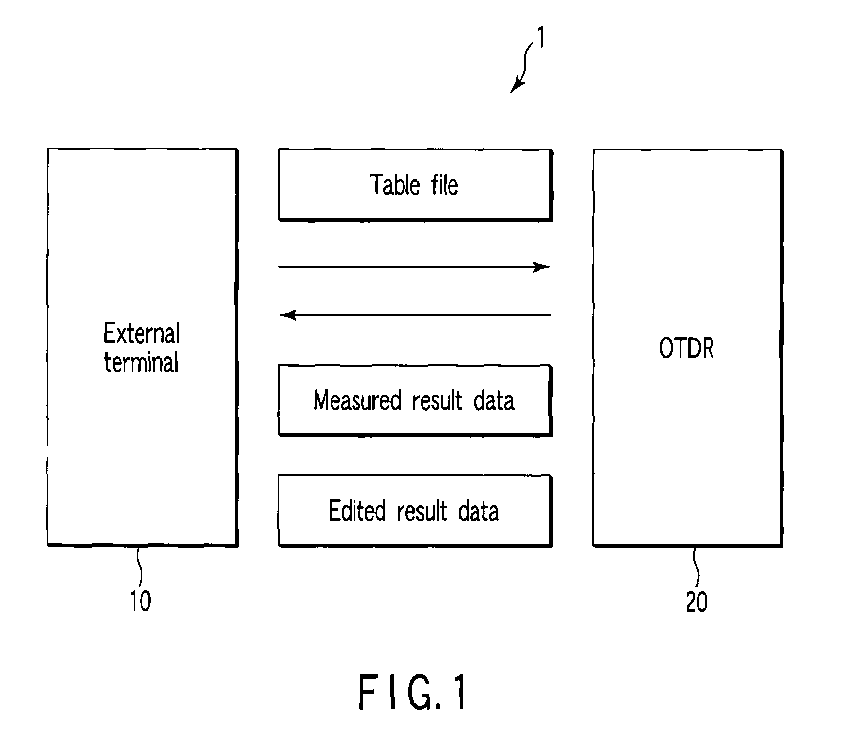
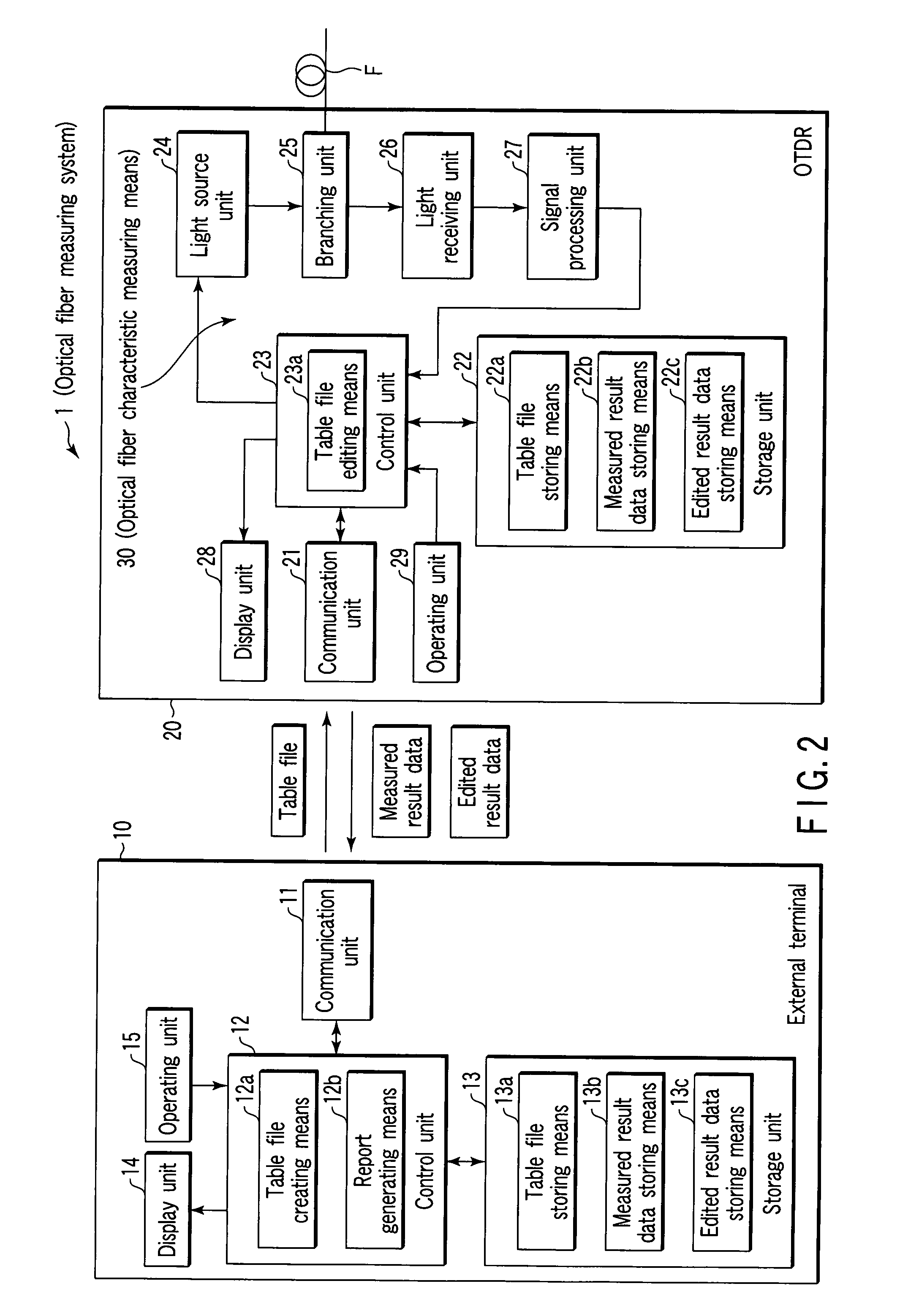
[0120]In accordance with the present invention, because measurement of an optical fiber is carried out based on a table file created in advance at an external terminal, it is possible to associate the measured optical fiber with measured data at the same time of measuring. Therefore, an attempt can be made to make operations in a laying / maintenance construction of the optical fiber more efficient, and there is no need to associate the measured optical fiber with the measured data in a report generating operation which is carried out after measuring an optical fiber. This makes it possible to eliminate the troublesomeness in report generation.
[0121]In accordance with the present invention, even when a situation which is different from planning of a table file created in advance is brought about, and the planning of the table file is edited, it is possible to store edited contents as edited result data, and to generate a report based on the measured result data and the edited result data. This makes it possible to easily carry out identification of measured data and management of measurement conditions.

Problems solved by technology

This brings about a problem that the report generation work is extremely troublesome.
However, even by such “sequential measurement”, in fact, there are cases in which the relevance between the file name set in advance and the optical fiber actually measured disappears due to a change in a file name set in advance, skipping of measurement of optical fibers depending on progress, changes in operations of a cable laying / maintenance construction, and the situation of a measuring site or an optical fiber.
Therefore, there is the problem that it is impossible to flexibly respond to the situation on-site by procedures of such “sequential measurement”.
Therefore, when an operator brings a file in which measured data of an optical fiber has been recorded back to an office to generate a report, it is sometimes necessary to verify the relevance between the measured data and the file name again, or to change the file name, and therefore, there is a problem that it requires more operation time, which is troublesome in the same way as a usual cable laying / maintenance construction.

Method used


Image

  • Optical time domain reflectometer, and optical fiber measuring method and optical fiber measuring system using the same
  • Optical time domain reflectometer, and optical fiber measuring method and optical fiber measuring system using the same
  • Optical time domain reflectometer, and optical fiber measuring method and optical fiber measuring system using the same

Examples


applied example 1

Skip Measurement

[0268]There are cases in which it is clear in advance that there are optical fibers F which cannot be actually measured because a certain optical fiber F is currently in the process of operation, or an optical fiber F is in the process of undertaking construction, although the plurality of optical fibers F serving as measuring objects have been laid down.

[0269]In such a case, at a point in time when a table file is created, it is possible to display in the display fields of optical fibers F serving as objects to be skipped so as to clarify that the measurements are skipped.

[0270]As a display example, for example, as shown in FIG. 11, a field of a corresponding optical fiber F is selected from among those in the table file, and it is set that the measurement is skipped at the external terminal 10 (for example, the line of the optical fiber F to be skipped is displayed in a different color or in italic type).

[0271]In accordance therewith, for example, as shown in FIG. ...

applied example 2

Both-End Measurements

[0273]As a method for measuring optical fibers F using the OTDR 20, there is both-end measurement as a method for executing measurements more precisely.

[0274]The both-end measurement is a method in which measured data measured from the both ends of an optical fiber F serving as a measuring object by the OTDR 20 are averaged, and the averaged value is regarded as the measured data of the optical fiber F serving as a measuring object.

[0275]However, in the case of measuring a plurality of optical fibers F, because it is difficult for one operator to measure the plurality of optical fibers F from the both sides, at least two or more operators are required.

[0276]In the case of the both-end measurements by a plurality of operators, an operation in which measured data measured respectively by different operators are respectively identified as measured data in which what optical fiber F has been measured from which side, is bothersome.

[0277]Further, in the both-end meas...


PUM


Abstract

In order to easily and efficiently carry out various characteristic evaluations of optical fibers which have been laid down, a table file which is for carrying out association of optical fibers serving as measuring objects with measured data when the optical fibers have been measured, based on optical fiber management information provided in advance of undertaking a cable laying / maintenance construction, such as various types of information on the optical fibers serving as measuring objects, and information on a construction site, and the like, is created at an external terminal. An OTDR measures the optical fibers serving as measuring objects based on the table file created at the external terminal, and stores measured result data in which the measured optical fibers and measured data of the optical fibers have been associated with one another, and edited result data expressing edited contents when the table file and the measured result data have been edited. The external terminal generates a report based on the measured result data and the edited result data stored in the OTDR.

Description

[0001]This application is a U.S. National Phase Application Under 35 USC 371 of International Application PCT / JP2006 / 321762 filed Oct. 31, 2006.TECHNICAL FIELD[0002]The present invention relates to an optical time domain reflectometer, and an optical fiber measuring method and an optical fiber measuring system using the same, and particularly to an optical time domain reflectometer using a technique in which it is possible to easily and efficiently carry out various characteristic evaluations of fault localization, loss measurement, and the like of optical fibers including multicore optical fibers which are laid down, and also relates to an optical fiber measuring method and an optical fiber measuring system using the same.BACKGROUND ART[0003]Conventionally, in order to inspect the states of connection points and other fault points of optical fibers laid down as optical communication lines, an optical time domain reflectometer (OTDR), more commonly known as an optical pulse tester, ...

Claims


Application Information

Patent Timeline
Patent Type & Authority Patents(United States)
IPC IPC(8): G06F19/00G01M11/00
CPCG01M11/3136
Inventor NAKAYAMA, NORIOMIYAKE, YASUHIROIMAZU, YOSHIFUMIHORI, SHIGEOMASUHARA, KEITA
Owner ANRITSU CORP
Learn More