
Image projecting apparatus

An image projection and equipment technology, applied in the field of image projection equipment, can solve the problems of increasing the overall noise, complex structure of the cooling system, and difficult to use.

Inactive Publication Date: 2010-04-14
SAMSUNG ELECTRONICS CO LTD
View PDF4 Cites 0 Cited by
  • Summary
  • Abstract
  • Description
  • Claims
  • Application Information

AI Technical Summary

Problems solved by technology

[0006] However, when multiple cooling fans are employed, these cooling fans increase the overall noise generated by the image projection device
When the guide device is used, the structure of the cooling system becomes relatively complicated
The use of the above two solutions requires an increase in the volume of the cooling system, so it is not easy to use these two solutions in small-sized image projection equipment

Method used


Image

  • Image projecting apparatus
  • Image projecting apparatus
  • Image projecting apparatus

Examples


Embodiment Construction

[0031] Reference will now be made in detail to exemplary embodiments of the invention, examples of which are illustrated in the accompanying drawings.

[0032] Although an exemplary embodiment of the present invention described below is an image projecting apparatus including a digital micromirror device (DMD) panel as an image device, the present invention is not limited to such an image projecting apparatus.

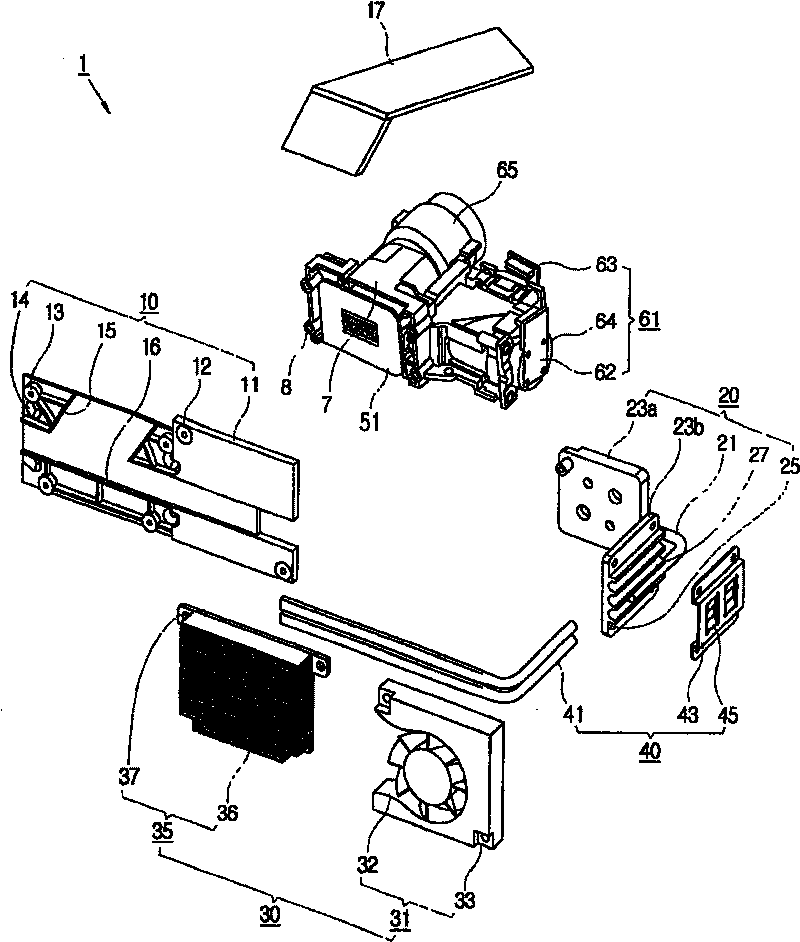
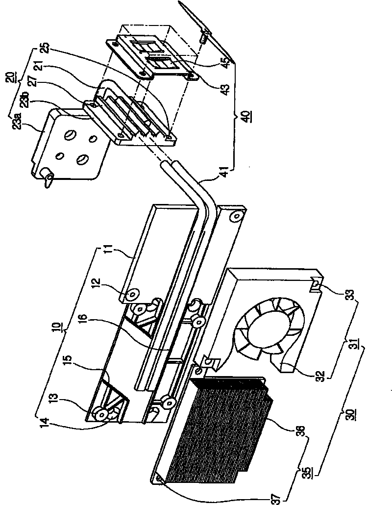
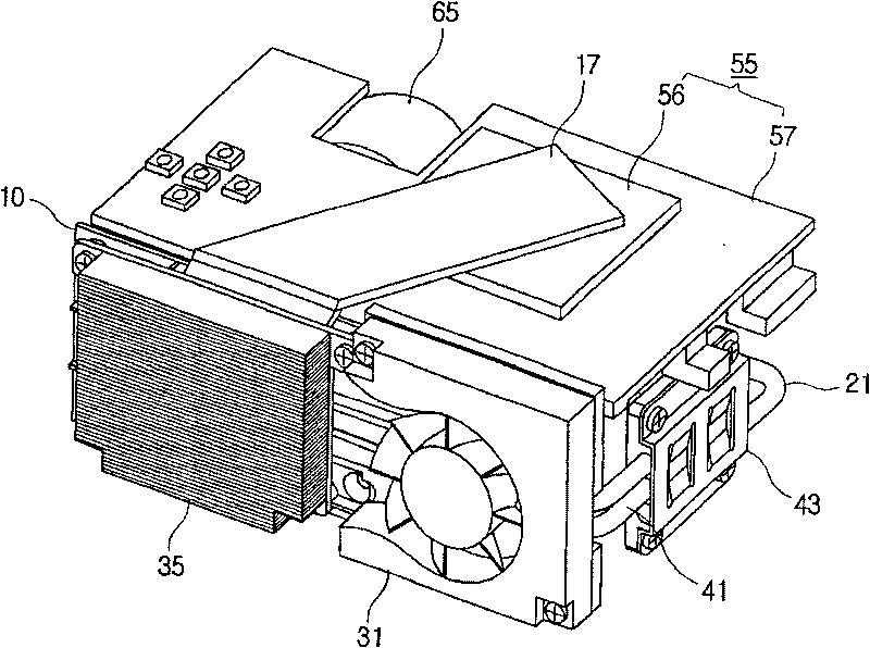
[0033] figure 1 is an exploded perspective view of the image projecting apparatus 1 according to the exemplary embodiment of the present invention. Such as figure 1 As shown, the image projection device 1 includes a housing 3 ( Figure 5 ), the main body frame 7 accommodated in the casing 3 and the light emitting part 61 supported by the main body frame 7 . The image device 51 forms an image by using light emitted from the light emitting portion 61 . The first heat absorbing portion 10 absorbs heat generated by the image device 51 . The second heat absorbing part ...


PUM


Abstract

The present invention relates to an image projecting apparatus having a main body frame, a light generating part supported by the main body frame, and an image device forming images by using light irradiated by the light generating part. The image projecting apparatus includes a first heat absorbing part that absorbs heat generated by the image device. A second heat absorbing part absorbs heat generated by the light source. A heat dissipating part transfers heat to one of the first heat absorbing part and the second heat absorbing part. A combining part separably combines the first heat absorbing part and the second heat absorbing part to transfer heat between the first heat absorbing part and the second heat absorbing part. Thus, the present invention provides an image projecting apparatus having a modularized cooling apparatus to improve work efficiency in manufacturing and repairing the image forming apparatus.

Description

technical field [0001] The present invention relates to an image projection device. More particularly, the present invention relates to an image projection device with improved cooling means. Background technique [0002] Generally, an image projection apparatus includes an optical system having an image device and a light source that supplies light to the optical system, and enlarges and projects an image formed by the image device onto a screen. [0003] Recently, image projection apparatuses have been developed toward smaller size and lighter weight, but this has caused some problems. Among these problems, one is how to dissipate the heat generated inside the image projection device to the outside. [0004] An image projecting device includes a plurality of heat generating units that inevitably generate heat during operation. For example, light sources such as lamps, LEDs, etc. emit heat in addition to emitting light. The emitted heat may degrade the functions of circ...

Claims


Application Information

Patent Timeline
Patent Type & Authority Patents(China)
IPC IPC(8): G03B21/16
CPCH04N9/3144G03B21/16G03B21/14
Inventor 禹成济金元年姜秉助
Owner SAMSUNG ELECTRONICS CO LTD
Learn More