Substrate carrier

A technology for substrate conveying and conveying devices, which is applied in the direction of photolithographic process exposure devices, conveyor objects, transportation and packaging, etc., can solve the problems of limiting the operating range of other conveying arms, reducing the degree of freedom of conveying arm operation, and complicated control, etc., to achieve Improvement of conveying efficiency, simplification of operation control, and increase of operational freedom

Inactive Publication Date: 2007-01-31
TOKYO ELECTRON LTD
View PDF1 Cites 6 Cited by
  • Summary
  • Abstract
  • Description
  • Claims
  • Application Information

AI Technical Summary

Problems solved by technology

[0005] However, in the substrate transfer apparatus of the above-mentioned prior art, since a plurality of arms are stacked in the vertical direction and the transfer arms are moved in the vertical direction integrally, the operation of each transfer arm is limited by the operation of other transfer arms.
For example, during the operation of one transfer arm and the transfer of the substrate, the direction and height of the other transfer arms are determined, which limits the operating range of the other transfer arms.
Therefore, the degree of freedom of operation of each transfer arm is reduced, so that, for example, the control of determining the operation sequence of the transfer arms in order to efficiently transfer a plurality of substrates in the coating and development processing system becomes complicated.
In addition, there is a limit to improving substrate transfer efficiency.

Method used


Image

  • Substrate carrier
  • Substrate carrier
  • Substrate carrier

Examples


Embodiment Construction

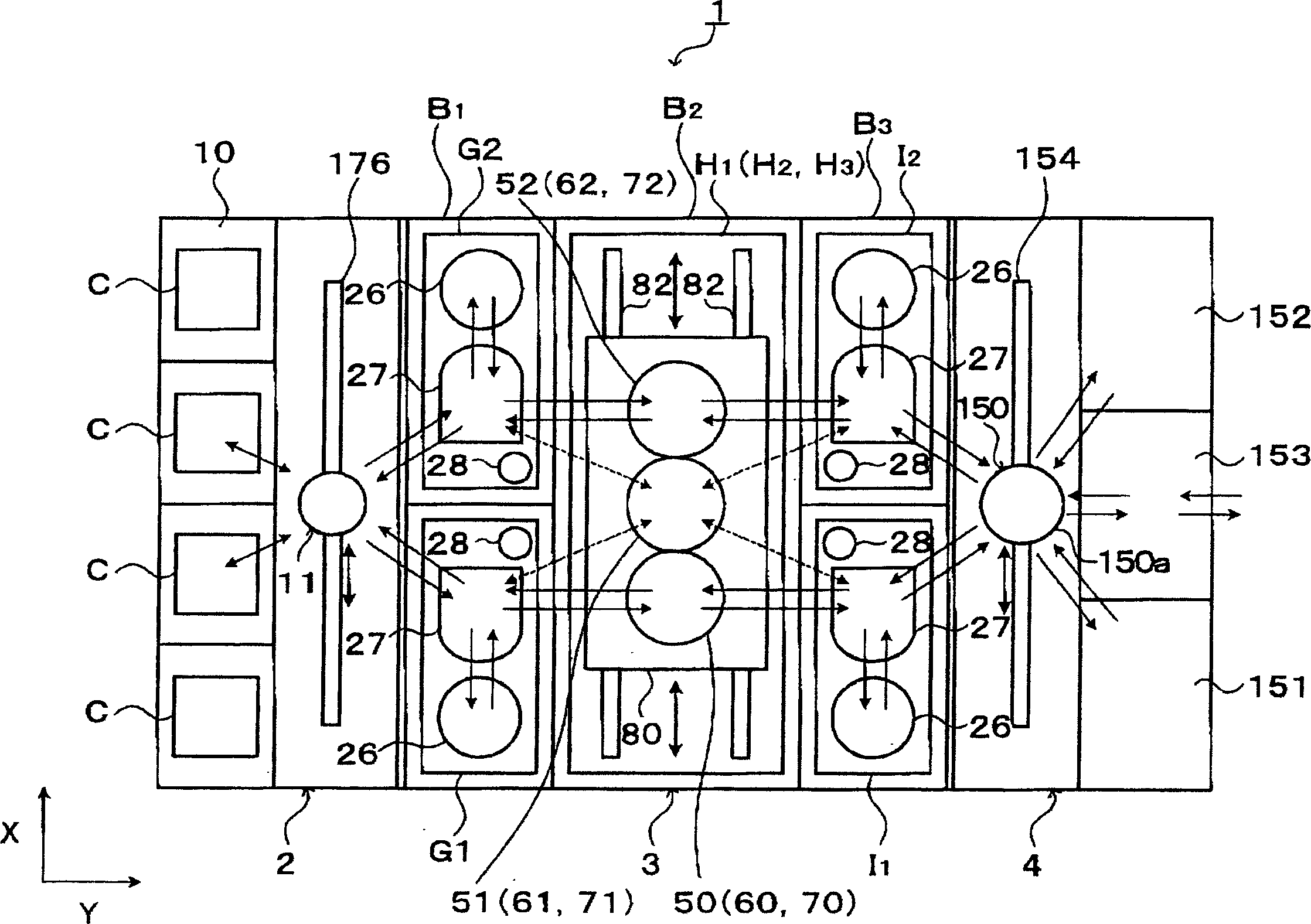
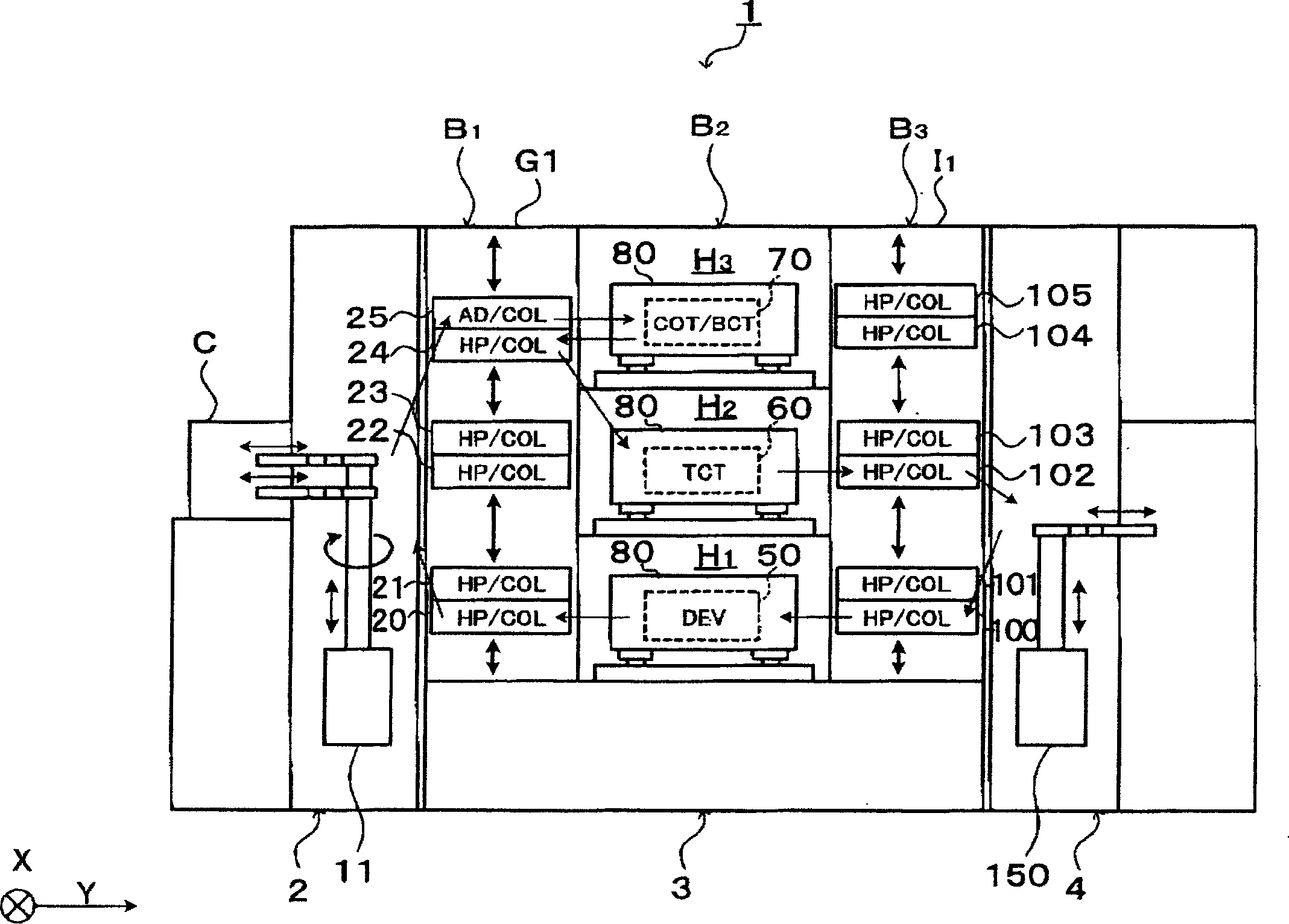
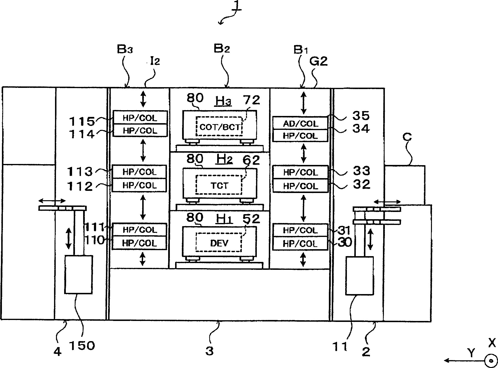
[0028] Next, the best mode for carrying out the present invention will be described. figure 1 It is a plan view showing a schematic configuration of a substrate processing system 1 equipped with a substrate transfer device according to the present embodiment.

[0029] The substrate processing system 1 includes a configuration in which a cassette station 2 such as figure 1 As shown, it loads and unloads, for example, 25 wafers W from the outside to the substrate processing system 1 in units of cassettes, and loads and unloads wafers W from the cassette C; A plurality of units that perform various processes in the photolithography process; and an interface unit 4 that is provided adjacent to the process station 3 and that transfers the wafer W to and from an exposure device (not shown). The box station 2, the processing station 3 and the interface part 4 face the Y direction ( figure 1 The left and right directions) are connected in series.

[0030] On the box station 2, a bo...


PUM


Abstract

The present invention includes a plurality of carrier arms provided close to each other, each of the carrier arms for supporting a substrate and carrying the substrate in the horizontal direction. The plurality of carrier arms are arranged such that carriage paths thereof overlap one on the other in plan view, each of the paths for carrying-in / out the substrate to / from a processing unit or a substrate housing cassette, and each of the plurality of carrier arms is independently movable in the vertical direction and is capable of passing the other in the vertical direction without interfering with each other. According to the present invention, in the carrier including the plurality of carrier arms, the degrees of freedom of the carrier arms are increased to improve the substrate carriage efficiency.

Description

technical field [0001] The invention relates to a substrate conveying device. Background technique [0002] For example, in the photolithography process of the manufacturing process of a semiconductor device, the following processes are continuously performed: a resist coating process of applying a resist solution to a substrate such as a wafer, and a development process of developing the substrate after exposure. Various treatments such as heat treatment for heating and cooling substrates. [0003] The various treatments mentioned above are usually carried out in a coating and developing treatment system. The coating and development processing system includes, for example: a cassette station on which a cassette capable of accommodating a plurality of substrates is placed; and a processing station equipped with various processing units that perform resist coating on the substrates. treatment, development treatment, heat treatment, etc.; and an interface section for loading...

Claims


Application Information

Patent Timeline
Patent Type & Authority Applications(China)
IPC IPC(8): H01L21/677H01L21/00B65G49/07G03F7/20
CPCH01L21/67742H01L21/67276H01L21/67766H01L21/67778H01L21/6779H01L21/68707Y10S414/141
Inventor 清田健司
Owner TOKYO ELECTRON LTD
Why Eureka
Try Eureka