Method for direct bonding of orthodontic brackets

A bracket and direct technology, applied in brackets, medical science, dentistry, etc., can solve the problems of cumbersome indirect bonding and high technical requirements, and achieve the effect of easy popularization, reduced complexity, and reduced professional requirements

Active Publication Date: 2019-11-22
张正朴
View PDF9 Cites 1 Cited by
  • Summary
  • Abstract
  • Description
  • Claims
  • Application Information

AI Technical Summary

Problems solved by technology

[0016] The present invention provides a method for direct bonding of brackets aiming at the shortcomings of in

Method used


Image

  • Method for direct bonding of orthodontic brackets
  • Method for direct bonding of orthodontic brackets
  • Method for direct bonding of orthodontic brackets

Examples


Embodiment 1

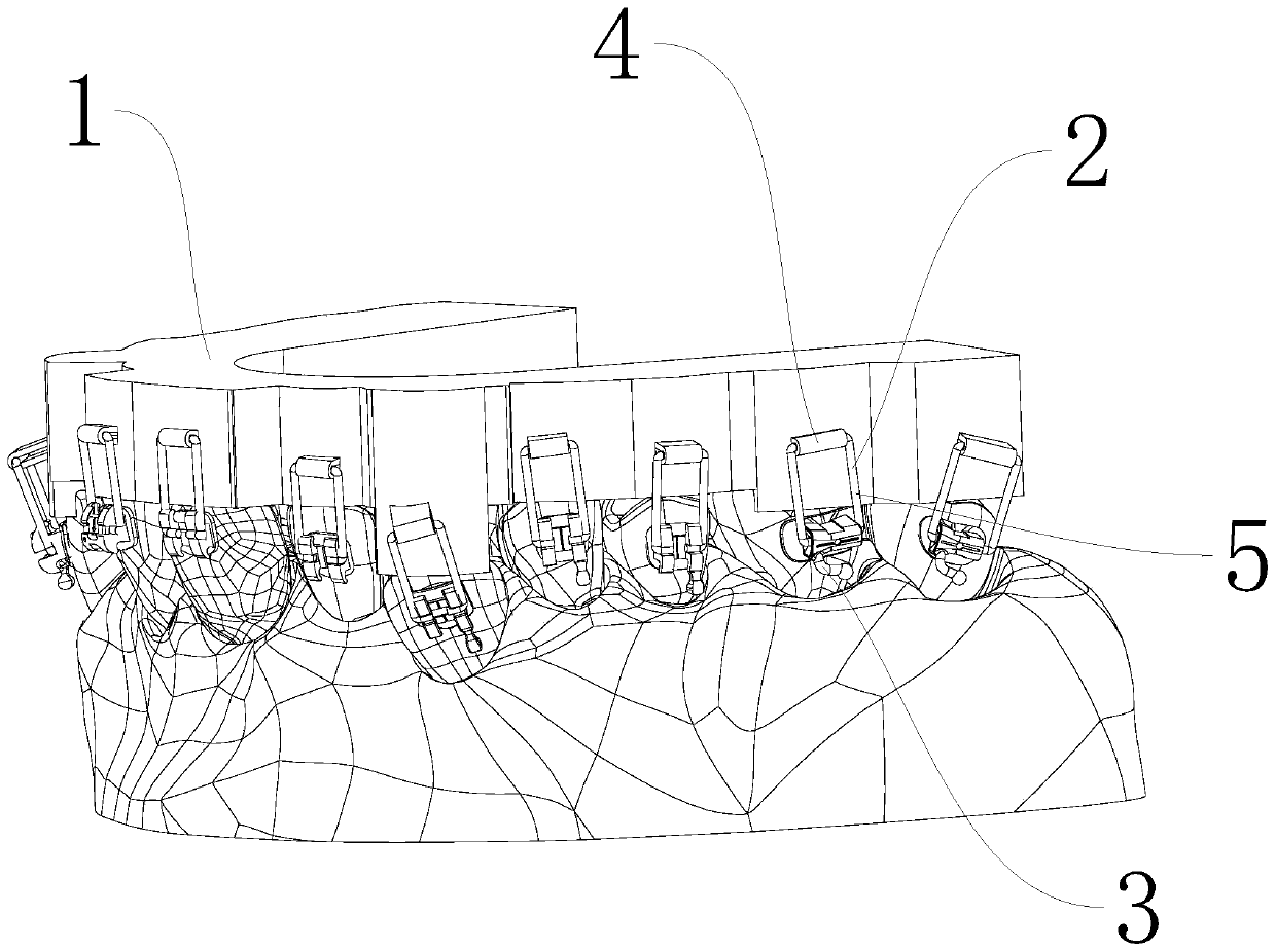
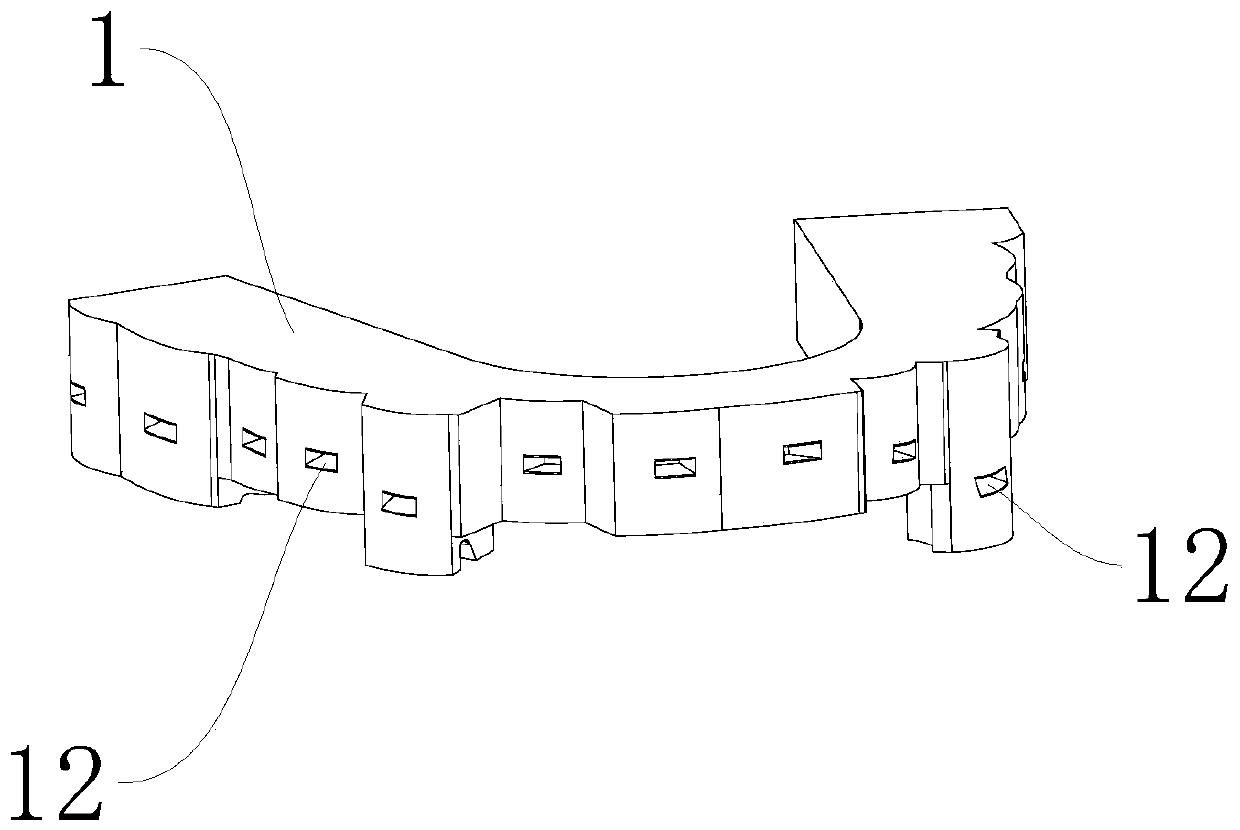
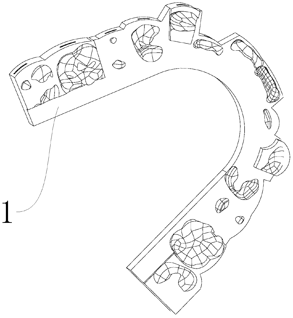
[0069] Such as figure 1 indivual figure 2 As shown, a method for direct bonding of brackets includes a tray 1 and a mounting frame 2, each mounting frame 2 is used to install a bracket 3, and the mounting frame 2 includes a bracket 4 and a positioning clip 5,

[0070] Tray 1, used as a support base for installing the mounting frame 2,

[0071] The bracket 4 is used as a fixed support, one end of which is connected and fixed to the lingual or labial side of the tray 1;

[0072] The positioning clip 5, as a rotating part, is used to connect with the bracket 3 to adjust the position of the bracket 3;

[0073] The positioning clip 5 includes a damping shaft 6, which cooperates with the bracket 4, and the positioning clip 5 rotates around the bracket 4 through the damping shaft 6, and the bracket 4 and the tray 1 are integrally formed or detachable. The origin of the definition of the damping shaft 6 is that during the installation of the bracket 3 , when the damping shaft 6 ro...

Embodiment 2

[0103] A method for direct bonding of brackets, this embodiment includes the technical solution in Example 1, and also includes the following supplementary technical solution: the distance between the inner walls of the assembly space 10 connecting the parts of the installation groove 7 is smaller than the inner diameter of the installation groove 7 Dimensions, the assembly space 10 of the part connecting the installation groove 7 is the part of the installation groove 7 away from the end of the connecting part 11 . This structural design can ensure that the damping shaft 6 enters the installation slot 7 against a certain resistance during installation to the installation slot 7 , and prevents the damping shaft 6 from slipping in the installation slot 7 . In this embodiment, the specific implementation method of this structure is to set up arc-shaped grooves on the adjacent sides of the first splint 8 and the second splint 9, so that the distance between the two arc-shaped groo...

Embodiment 3

[0105] A method for direct bonding of brackets. This embodiment includes the technical solution in Example 2, and also includes the following supplementary technical solution: the end of the installation groove 7 near the connecting portion 11 is connected with a deformation groove 18 . The function of the deformation groove 18 is that when the installation groove 7 is deformed by force, the deformation force can be transferred to the deformation groove 18 to facilitate the deformation of the installation groove 7, and at the same time, it can avoid excessive friction between the installation groove 7 and the damping shaft 6 As a result, stagnation occurs between the installation groove 7 and the damping shaft 6 .


PUM


Abstract

The invention relates to the field of orthodontic bracket bonding, and discloses a method for direct bonding of orthodontic brackets. The method comprises the following steps: step 1, constructing a three-dimensional digital occlusal model, and generating a dental arch morphology in a simulation manner; step 2, constructing virtual orthodontic brackets; step 3, importing the three-dimensional occlusal model into an orthodontic software, and automatically positioning clinical crown centers of teeth by the orthodontic software; step 4, performing imitative positioning on the orthodontic bracketsat the clinical crown centers according to requirements and a pre-designed correction plan; step 5, forming an occlusal tray model according to a tooth morphology of a three-dimensional dental cast,step 6, according to data of an installation bracket and the positions of the orthodontic brackets on the tooth surface, arranging insertion holes corresponding to each orthodontic bracket in the trayin a simulation manner; step 7, outputting a 3D print file of the tray; and step 8, performing 3D printing on the tray. The installation bracket is also arranged, the physical orthodontic brackets are installed on the installation bracket, and the installation bracket is inserted into the corresponding insertion holes of the orthodontic brackets. The bonding method provided by the invention has the characteristics of reliable bonding, high bonding efficiency and high bonding accuracy.

Description

technical field [0001] The invention relates to the field of bracket bonding, in particular to a method for directly bonding brackets. Background technique [0002] At present, in the process of orthodontic treatment of oral teeth, the orthodontic bracket is fixed on the tooth surface, and the archwire passes through the archwire groove (also known as the square wire groove) on the bracket, and is connected by a ligature rubber ring or a ligature wire. The steel wire directly ligates the arch wire to the arch wire groove of the bracket, and the correction force of the arch wire is transmitted to the teeth through the bracket, so that the teeth move as expected to achieve the purpose of orthodontics. Therefore, the bracket has strict requirements on the sticking position on the teeth, because this is an important factor affecting the correction effect. There are two ways to choose the position of the traditional bracket paste, one is to mark on the teeth according to experie...

Claims


Application Information

Patent Timeline
IPC IPC(8): A61C7/16
CPCA61C7/002A61C7/16
Inventor 张正朴
Owner 张正朴
Why Eureka
Try Eureka