Information recording medium
A technology of information recording and media, applied in information storage, data recording, temperature recording, etc., can solve the problems of inability to ensure the stability of amorphous phase, decrease of signal quality, decrease of crystallization temperature, etc., and achieve high-quality record preservation High performance, good record retention, and high erasing performance
- Summary
- Abstract
- Description
- Claims
- Application Information
AI Technical Summary
Problems solved by technology
Method used
Image
Examples
Embodiment approach 1
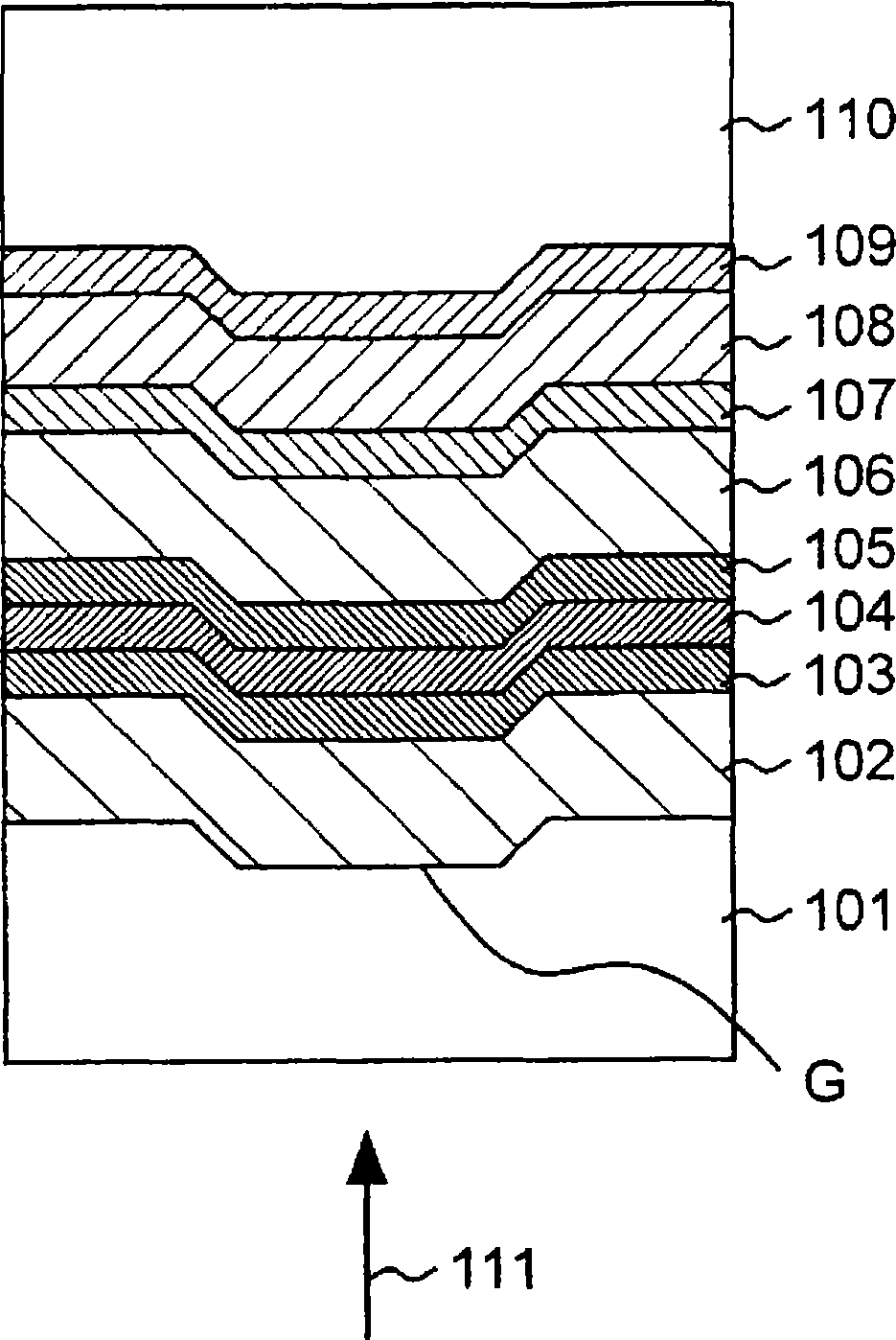
[0092] As the first embodiment of the present invention, an example of an optical information recording medium that uses laser light to perform recording and reproduction of information will be described. figure 1 Shows a partial cross section of the optical information recording medium.
[0093] Such as figure 1 The information recording medium 100 shown has the following structure: a first dielectric layer 102 is formed on one surface of a substrate 101, a first interface layer 103 is formed on the surface of the first dielectric layer 102, and a first interface layer 103 is formed on the surface of the first interface layer 103. The recording layer 104 is formed on the surface, the second interface layer 105 is formed on the surface of the recording layer 104, the second dielectric layer 106 is formed on the surface of the second interface layer 105, and the light absorption correction is formed on the surface of the second dielectric layer 106 In the layer 107, a reflective ...
Embodiment approach 2
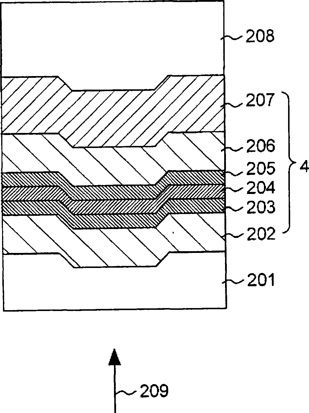
[0148] As the second embodiment of the present invention, an example of an optical information recording medium that uses laser light to record and reproduce information will be described. figure 2 Shows a partial cross section of the optical information recording medium.
[0149] Such as figure 2 The illustrated information recording medium 200 has the following structure: a reflective layer 207 is formed on one surface of a substrate 208, a second dielectric layer 206 is formed on the surface of the reflective layer 207, and a second dielectric layer 206 is formed on the surface of the second dielectric layer 206. In the second interface layer 205, a recording layer 204 is formed on the surface of the second interface layer 205, a first interface layer 203 is formed on the surface of the recording layer 204, and a first dielectric layer 202 is formed on the surface of the first interface layer 203, and further, A cover layer 201 is formed. The information recording medium of t...
Embodiment approach 3
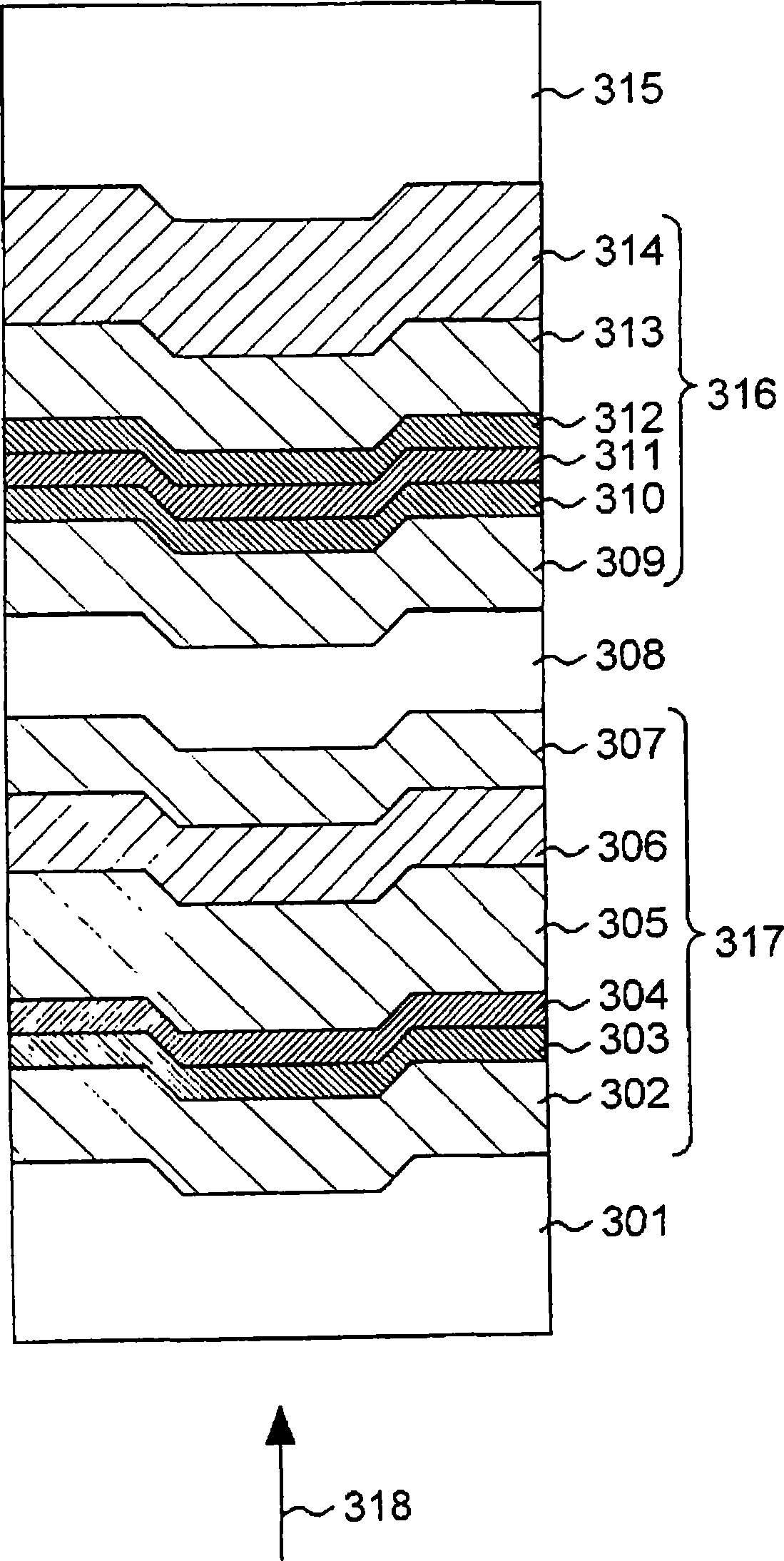
[0174] As the third embodiment of the present invention, an example of an optical information recording medium that uses laser light to record and reproduce information will be described. image 3 Shows a partial cross section of the optical information recording medium.
[0175] Such as image 3 The illustrated information recording medium 300 has a structure in which a substrate 315, a second information layer 316, an intermediate layer 308, a first information layer 317, and a cover layer 301 are arranged in this order. In more detail, the second information layer 316 has a second reflective layer 314, a fifth dielectric layer 313, a third interface layer 312, a second recording layer 311, a second interface layer 310, and a Four dielectric layers 309. The intermediate layer 308 is formed on the surface of the fourth dielectric layer 309. The first information layer 317 is sequentially arranged with a third dielectric layer 307, a first reflective layer 306, a second dielectric...
PUM
| Property | Measurement | Unit |
|---|---|---|
| thickness | aaaaa | aaaaa |
| thickness | aaaaa | aaaaa |
| thickness | aaaaa | aaaaa |
Abstract
Description
Claims
Application Information
 - R&D Engineer
- R&D Manager
- IP Professional
- Industry Leading Data Capabilities
- Powerful AI technology
- Patent DNA Extraction
Browse by: Latest US Patents, China's latest patents, Technical Efficacy Thesaurus, Application Domain, Technology Topic, Popular Technical Reports.
© 2024 PatSnap. All rights reserved.Legal|Privacy policy|Modern Slavery Act Transparency Statement|Sitemap|About US| Contact US: help@patsnap.com


