Magnetic sensor and its manufacturing method

A magnetic sensor and magnetoresistive technology, applied in the direction of converting the sensor output, the magnitude/direction of the magnetic field, the resistance of the magnetic field control, etc., can solve the problems of manufacturing difficulties, rising manufacturing costs, and narrow spacing of magnetoresistive elements, to prevent spacing The effect of narrowing down, reducing adverse effects, and preventing the decrease in the degree of freedom of arrangement

Inactive Publication Date: 2007-01-31
SANKYO SEIKI MFG CO LTD
View PDF1 Cites 8 Cited by
  • Summary
  • Abstract
  • Description
  • Claims
  • Application Information

AI Technical Summary

Problems solved by technology

However, in the invention described in Patent Document 1, since the number of magnetoresistive elements that cancel each other's harmonics is fixed, the intervals between the magnetoresistive elements are extremely narrow as a whole, and there is a problem. The problem that manufacturing becomes difficult and manufacturing cost rises
[0019] In this way, from the viewpoint of uniformity of thermal performance and improvement of recognition accuracy, it is preferable to increase the number of magnetoresistive elements for canceling each harmonic. However, in the invention described in Patent Document 1, Since the number of magnetoresistive elements that cancel each other's harmonics is fixed, as a result, if the number of magnetoresistive elements is increased, manufacturing will become difficult and manufacturing costs will increase

Method used


Image

  • Magnetic sensor and its manufacturing method
  • Magnetic sensor and its manufacturing method
  • Magnetic sensor and its manufacturing method

Examples


Embodiment 1

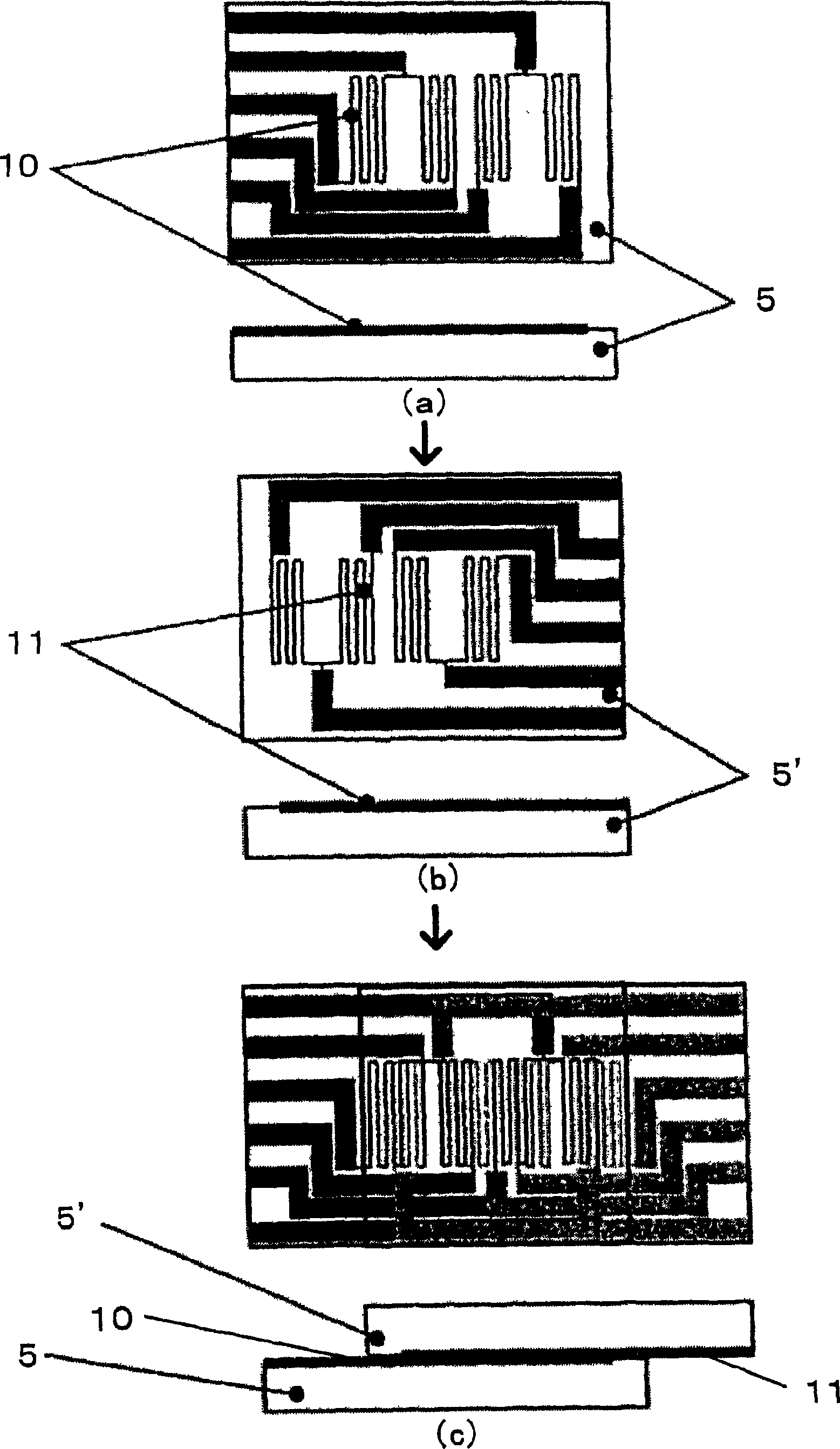
[0197] First, in Figure 17 In the formation method of the magnetoresistive pattern shown in (a), the signal period λ was set to 0.8 mm, and the output (displacement detection signal) Out was measured. As a result, if the Figure 17 In the method of forming the magnetoresistive pattern shown in (a), not only the 3rd and 5th, as well as the 2nd and 4th harmonic components are all eliminated, but also the interference of the displacement detection signal due to the 12 magnetoresistive elements , the 9th harmonic components are all eliminated, and the 7th harmonic components are reduced by 72%. It is known that if this Figure 17 With the method of forming the magnetoresistive pattern shown in (a), the total distortion up to the 9th harmonic component can be simultaneously reduced.


PUM


Abstract

A magnetic sensor comprises magnetoresistor thin films used in view of improvement of identification accuracy of operation of the magnetic sensor so as to prevent degradation of the degree of freedom of arrangement attributed to the narrow intervals between the magnetoresistor thin films. The number of magnetoresistive elements for canceling the harmonics can be increased to an extent that the production of the magnetic sensor does not became difficult while flexibly adjusting the intervals between magnetoresistive elements. The thermal characteristics are uniformed and the identification accuracy is improved. The magnetic sensor has magnetoresistance pattern where magnetoresistor thin films are formed on a substrate, and the magnetoresistance pattern is composed of A-phase and B-phase magnetoresistance patterns which output two signals having phases which are different by 90 DEG. The magnetic sensor is characterized in that the magnetoresistance pattern is formed by combining two substrates.

Description

technical field [0001] The present invention relates to a magnetic sensor for detecting displacement, such as movement amount, position, angle, etc. of a movable object to be detected, and a method for manufacturing the same, in particular, to a magnetic sensor capable of improving the degree of freedom of arrangement of a magnetoresistive thin film formed on a magnetoresistive pattern of a magnetic sensor. Sensor and method of making the same. Furthermore, the present invention relates to a magnetic sensor capable of canceling a higher harmonic component superimposed on a fundamental wave component of a detected actual output signal by means of the arrangement of the magnetoresistive element. Background technique [0002] Conventionally, as a sensor for detecting the displacement amount of the displacement of the movable object to be detected, a magnetic sensor is used. As one form of such a magnetic sensor, for example, a multi-pole magnetized layer that is magnetized at ...

Claims


Application Information

Patent Timeline
Patent Type & Authority Applications(China)
IPC IPC(8): G01D5/245G01R33/02G01R33/09H01L43/08
Inventor 野口直之百濑正吾有贺英吉竹村政夫
Owner SANKYO SEIKI MFG CO LTD
Why Eureka
Try Eureka