Tire wheel assembly

一种组装体、车轮的技术,应用在车轮、充气轮胎、辐板式车轮等方向,能够解决隔板大小限制、变形、难以提高空腔共鸣音降低效果等问题,达到提高降低效果、分裂显著的效果

Inactive Publication Date: 2007-02-07
THE YOKOHAMA RUBBER CO LTD
View PDF1 Cites 2 Cited by
  • Summary
  • Abstract
  • Description
  • Claims
  • Application Information

AI Technical Summary

Problems solved by technology

[0004] However, in the above method, when the cross-sectional area of ​​the closed space is changed to increase the effect of reducing cavity resonance noise, the spacer may interfere with the deformation of the tire, or the rim assembly workability may be deteriorated.
Therefore, the size of the partition is limited, and it is difficult to increase the effect of reducing cavity resonance noise

Method used


Image

  • Tire wheel assembly
  • Tire wheel assembly
  • Tire wheel assembly

Examples


Embodiment Construction

[0031] Below, while referring to the attached Figure 1 The configuration of the present invention will be described in detail.

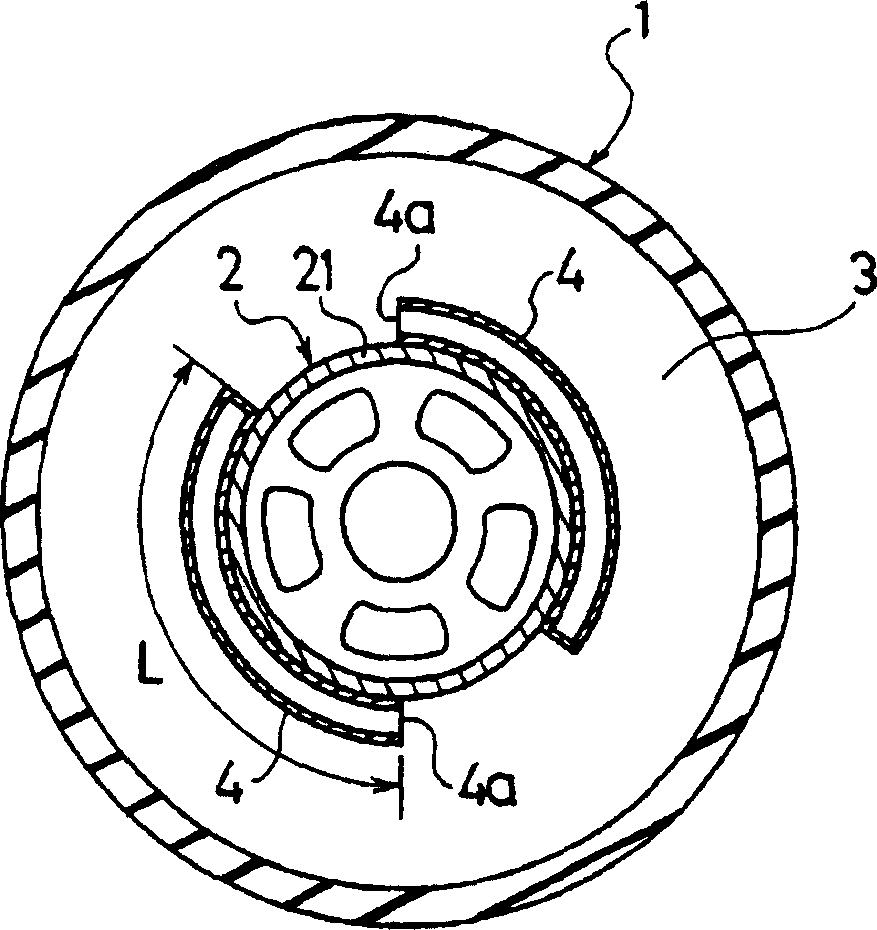
[0032] figure 1 It is a figure which schematically shows the tire wheel assembly of this invention. exist figure 1 Among them, 1 is the pneumatic tire and 2 is the wheel. The wheel 2 includes a rim 21 fitted to the pneumatic tire 1 . Furthermore, a cavity 3 is formed between the pneumatic tire 1 and the rim 21 of the wheel 2 . Furthermore, two pipes 4, 4 are formed on the tire and wheel assembly so as to open to the cavity.

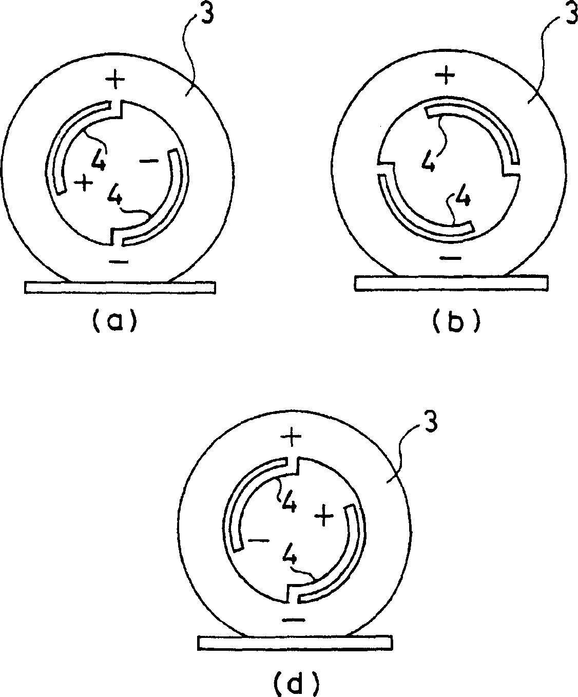
[0033] Each tube 4 has a reference length L approximately equivalent to 1 / 4 of the cavity resonance wavelength λ 0 length L, while one end is closed. The openings 4a of these tubes 4 are arranged at any one location on the circumference or at two opposing locations across the tire rotation axis.

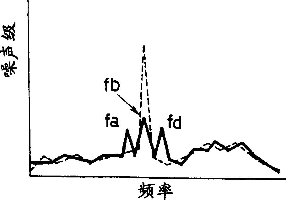
[0034] In the tire and wheel assembly constituted as described above, the vibration in the cavity 3 interferes with the vibr...


PUM


Abstract

Provided is a tire wheel assembly making it possible to effectively reduce cavity resonance noise without causing either negative influence on deformation of a tire or deterioration in rim assembling workability. A tire wheel assembly of the present invention includes a pneumatic tire, and a wheel provided with a rim fitted with the pneumatic tire, and forms a cavity portion between the pneumatic tire and the rim. The tire wheel assembly comprises at least one tube, which has one end thereof closed while having a length of 55% to 110% of a reference length L0 corresponding to one fourth of a cavity resonance wavelength, is provided so as to open to the cavity portion.

Description

technical field [0001] The present invention relates to a tire and wheel assembly including a pneumatic tire and a wheel, and more specifically, to a tire and wheel assembly capable of effectively reducing cavity resonance noise. Background technique [0002] In pneumatic tires, one of the causes of noise is cavity resonance sound caused by vibration of air filled inside the tire. This cavity resonance sound is generated by the fact that when the tire is rotated, the tread portion vibrates due to unevenness of the road surface, and the vibration of the tread portion vibrates the air inside the tire. [0003] As a method of reducing the noise generated by such a cavity resonance phenomenon, there is a proposal to shorten the time of resonance at a single resonance frequency by making the cross-sectional area of ​​the closed space formed by the tire and the wheel change in the tire circumferential direction (for example, refer to Patent Document 1). More specifically, in ord...

Claims


Application Information

Patent Timeline
Patent Type & Authority Applications(China)
IPC IPC(8): B60B21/02B60C5/00B60B21/12B60C19/00
CPCB60B3/02B60B21/02B60B21/026B60B21/00B60B3/005B60C19/002Y10T152/10522Y10T152/10495
Inventor 池田俊之丹野笃
Owner THE YOKOHAMA RUBBER CO LTD
Why Eureka
Try Eureka