

Sound absorbing device
A sound-absorbing device and sound technology, applied in the field of sound-absorbing devices, can solve problems such as effect reduction, noise deterioration, and noise reduction
- Summary
- Abstract
- Description
- Claims
- Application Information
AI Technical Summary
Problems solved by technology
Method used
Image

Examples
no. 1 approach
[0065] A first embodiment will be described with reference to the drawings. The sound absorbing device of the present embodiment is installed in, for example, a vehicle air conditioner or a blower duct, and absorbs sound propagating in the air.
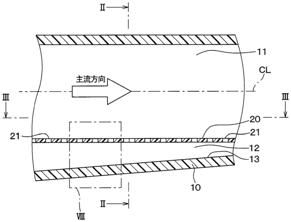
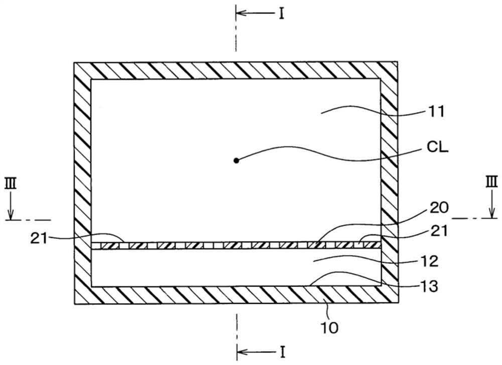
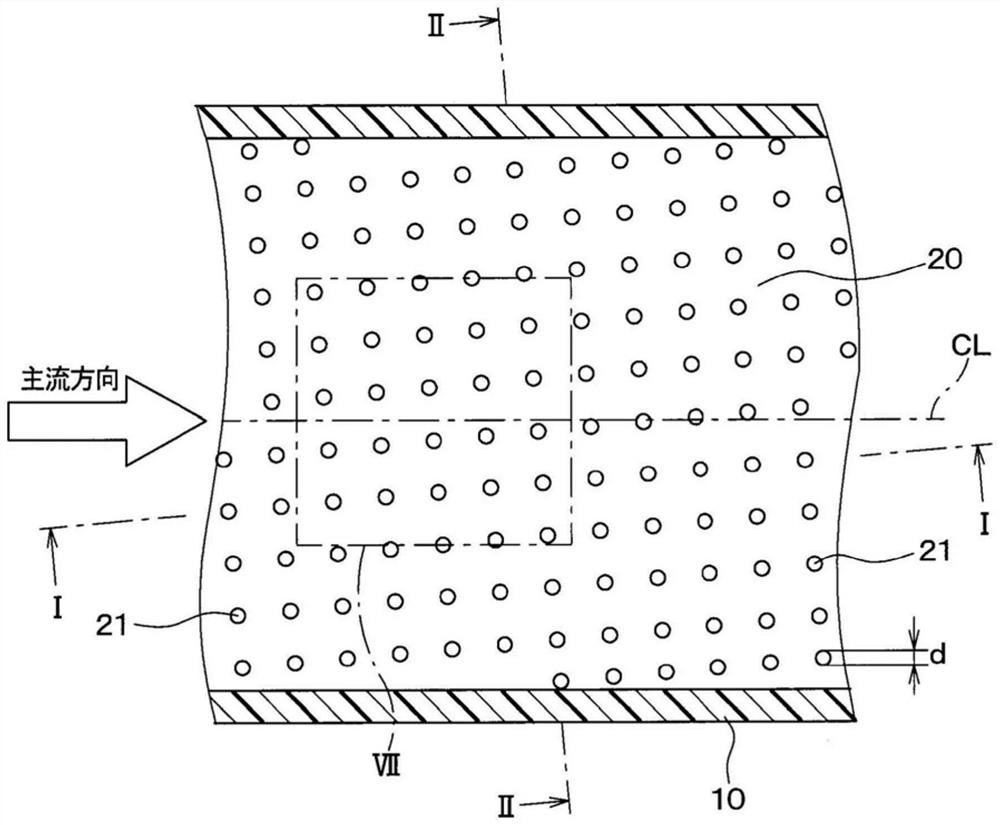
[0066] Such as Figure 1 ~ Figure 3 As shown, the sound absorbing device includes a passage member 10, a fine perforated plate 20, and the like. The passage member 10 is formed, for example, in a rectangular cross-section, and has a passage for air to flow inside. In addition, the cross-sectional shape of the passage member 10 is not limited to a rectangular shape, and various shapes such as a circle, an ellipse, a polygon, or a combination thereof may be employed.
[0067] exist figure 1 and image 3 In , the main flow direction of the air flowing in the passage of the passage member 10 is indicated by a hollow arrow. In addition, in the present embodiment, the main flow direction of the air flowing in the passage of the passage...
no. 2 approach
[0097] A second embodiment will be described. Compared with the first embodiment, the arrangement of the plurality of through-holes 21 penetrating through the micro-perforated plate 20 is changed in the second embodiment. Others are the same as the first embodiment, so only the differences from the first embodiment will be described.
[0098] Such as Figure 10 As shown, in the second embodiment, the plurality of through-holes 21 penetrating the fine perforated plate 20 are randomly arranged. In other words, the plurality of through holes 21 are randomly arranged without any regularity. exist Figure 10 In , an imaginary line including the center of the predetermined through-hole 21 and parallel to the centerline CL of the passage is indicated by a dashed-dotted line L1. In addition, an imaginary line including the center of the designated through-hole 21 and perpendicular to the centerline CL of the passage is indicated by a dashed-dotted line L2. Viewed from these two im...
no. 3 approach
[0102] A third embodiment will be described. Compared with the first embodiment and the like, the third embodiment has the thickness of the air layer 12 changed, and the others are the same as the first embodiment and the like, so only the parts different from the first embodiment and the like will be described.
[0103] Such as Figure 11 As shown, in the third embodiment, the inner wall surface 13 of the passage member 10 has a shape curved from the upstream side toward the downstream side. Therefore, the distance H between the inner wall surface 13 of the passage member 10 and the fine perforated plate 20 changes from the upstream side to the downstream side. Therefore, among the plurality of through holes 21 , the distance H between the inner wall surface 13 of the passage member 10 and the through holes 21 is different at least between adjacent through holes 21 . That is, between adjacent through holes 21 , the thickness of the air layer 12 between the inner wall surfac...
PUM
 Abstract
Description
Claims
Application Information