Wheel conveyor

A conveyor and wheel-type technology, applied in the direction of conveyor objects, transportation and packaging, rollers, etc., can solve the problems of lack of buffer function, vibration reduction function, static electric shock, impact noise, etc., and achieve convenient collection and recycling , easy cleaning effect

Inactive Publication Date: 2007-02-07
YAZAKI IND CHEM CO LTD
View PDF0 Cites 5 Cited by
  • Summary
  • Abstract
  • Description
  • Claims
  • Application Information

AI Technical Summary

Problems solved by technology

[0006] In addition, there is no cushioning function or vibration damping function between the metal frame member and the metal wheel shaft, so there is also the following problem: when conveying articles, if there is a bump or a difference in height, it will cause an impact and cause a shock. Damage the item or make a crashing noise
Therefore, it cannot be said that it is a wheel conveyor with a silent structure.
[0007] Secondly, when the wheels are made of plastic, they are usually insulated, so due to the impact or friction of the transported items, it is easy to generate static electricity and become charged. When transporting items such as electronic parts, due to static electric shock And the possibility of breakage is high, which can become a big problem
Of course, there will also be a problem of electrostatic shock for operators using the wheel conveyor
Moreover, static electricity has the property of attracting dust, and if it is charged, it is easy to adhere to dust, so it will cause a big problem if it is used in an environment that needs to avoid dust

Method used


Image

  • Wheel conveyor
  • Wheel conveyor
  • Wheel conveyor

Examples


Embodiment 1

[0083] Hereinafter, the present invention will be described based on illustrated embodiments.

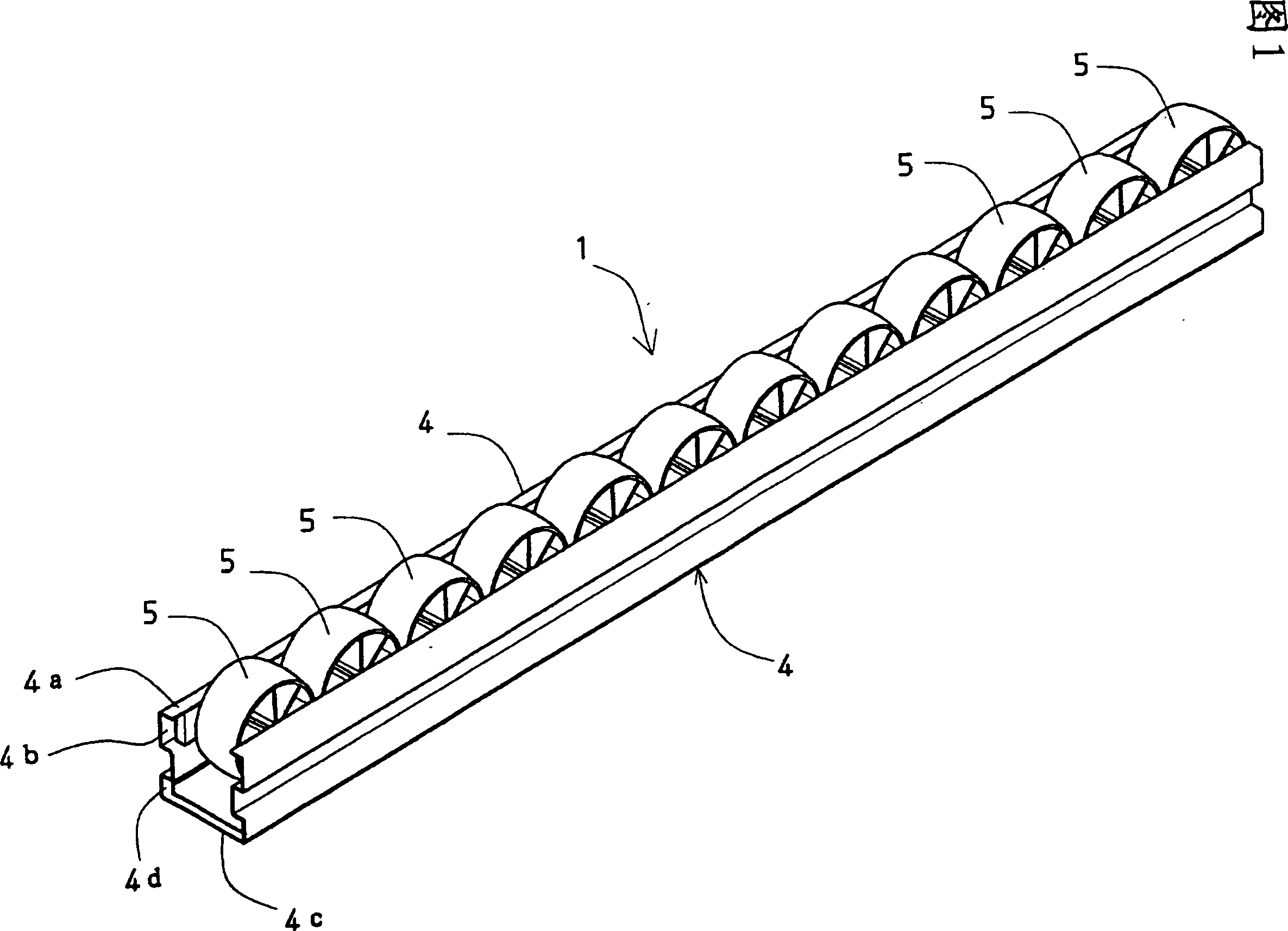
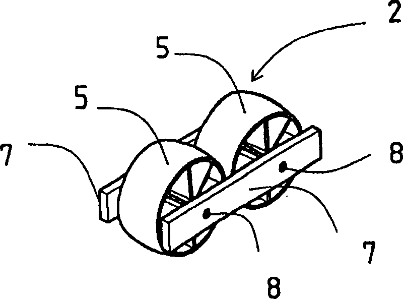
[0084] Fig. 1 shows an example of the completed state of the wheel conveyor 1 of the present invention. figure 2 An example of the wheel assembly 2 constituting the aforementioned wheel conveyor 1 is shown.

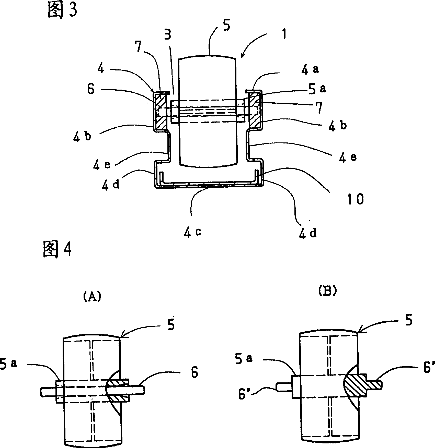
[0085] The wheel conveyor 1 includes a frame member 4 having an opening 3 (refer to FIG. 3 ) in a substantially grooved cross-sectional shape on the upper surface, and a wheel assembly 2 inserted into the groove of the frame member 4 . The following structure: the outer peripheral surfaces of the plurality of wheels 5 ... of the plurality of wheel assemblies 2 ... positioned and supported in the grooves of the frame member 4 protrude slightly upward from the aforementioned opening surface 3, and are arranged in a row .

[0086] Figure 4(A) and Figure 5 The illustrated wheel 5 has a hub pin 6 made of stainless steel that penetrates through the center of the hub 5 a and protr...


PUM


Abstract

A wheel conveyer formed by installing a wheel assembly having wheels and support plates disposed on both sides thereof and rotatably supporting the axles of the wheels in the grooves of frame materials, easily disassembled and cleaned, and having vibration damping function and dust collecting function. In the wheel assembly (2), the wheels (5) comprise axle pins (6), pin holes (8) are formed in the support plates (7), and the axle pins (6) are inserted into the pin holes (8) and rotatably supported on the pin holes. The shape of the frame material (4) in cross section is such that a first groove-shaped part (4b) formed continuously with a lip part (4a) supports the support plate (7) movably in the longitudinal direction, and a bottom part groove-shaped part (4d) formed continuously with a bottom wall (4c) is swelled outward from the mouth edge of the lip (4a). These two groove-shaped parts (4b) and (4d) are joined continuously to each other through a joining parts (4b) of the frame materials (4), and the plurality of wheels (5) are arranged in a row.

Description

technical field [0001] The present invention relates to the technical field of wheeled conveyors. The wheeled conveyors include: a metal frame member with an opening on the upper surface, and a generally groove-shaped cross-sectional shape uniform in the longitudinal direction; a plurality of plastic parts The wheel is rotatably supported in the groove of the frame member, and its outer peripheral surface protrudes slightly upward from the opening surface. More specifically, the present invention relates to a wheel conveyor that is constructed by fitting a wheel assembly into a groove of the aforementioned frame member, is easy to disassemble / clean, and has a vibration-damping function and a dust-collecting function. , wherein the wheel assembly includes a wheel, and support plates disposed on both sides of the wheel assembly to rotatably support the wheel shaft of the wheel. Background technique [0002] As a conventional wheel conveyor, for example, a conveyor disclosed i...

Claims


Application Information

Patent Timeline
Patent Type & Authority Applications(China)
IPC IPC(8): B65G39/12B65G13/11
CPCB65G39/12B65G13/11
Inventor 矢崎敦彦水尻寿嗣安藤亮菊地弘利植松文生
Owner YAZAKI IND CHEM CO LTD
Why Eureka
Try Eureka