
Automatic warehouse

A technology of automatic warehouse and labeling, which is applied in the field of automatic warehouse, can solve problems such as no records, and achieve the effect of increasing the degree of freedom

Inactive Publication Date: 2010-05-12
MURATA MASCH LTD
View PDF5 Cites 0 Cited by
  • Summary
  • Abstract
  • Description
  • Claims
  • Application Information

AI Technical Summary

Problems solved by technology

Although Patent Document 1 describes the idea of ​​attaching an ID tag to the tank container, it does not describe that the use of the ID tag eliminates the need for communication from the control unit to notify the transfer device of the storage location.

Method used


Image

  • Automatic warehouse
  • Automatic warehouse
  • Automatic warehouse

Examples


Embodiment

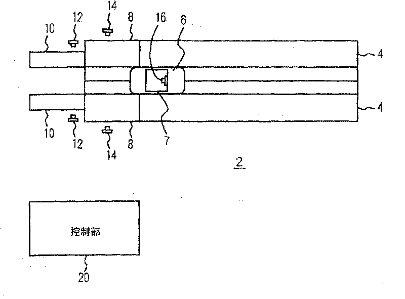
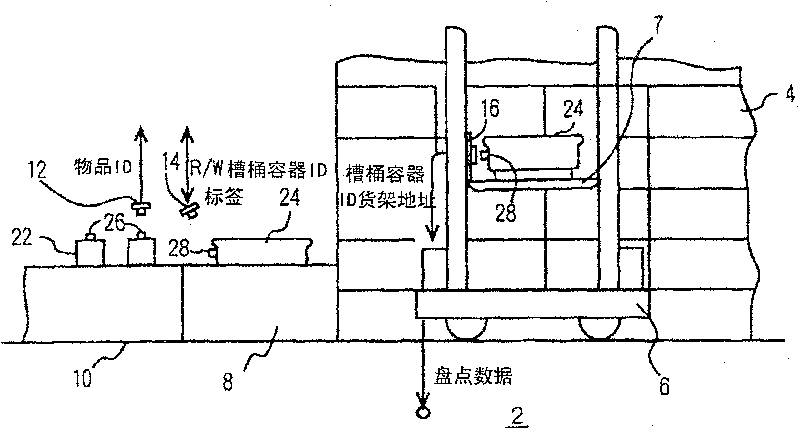
[0035] Figure 1 to Figure 6 The automatic warehouse of this embodiment is shown. In each figure, 4 is a shelf, which is set on both sides of the transporting device travel path in warehouses such as the stacking crane 6, and is designated as signs such as shelf addresses (1 row, 2 rows, 3 floors). 7 is the lifting platform of stacking crane 6. 8 and 8 are, for example, a pair of workstations, which may be divided into storage, delivery, and sorting, and may not be distinguished. In the embodiment, the stations 8, 8 are connected to the conveyor belt 10, 10, the conveyor belt 10 can be regarded as a part of the station 8 in a broad sense.

[0036] An ID reader 12 is installed on the conveyor belt 10 or the station 8 , an ID reader 14 serving also as a recorder is installed on the station 8 , and an ID reader 16 is installed on the elevator table 7 . Here, these ID readers are referred to as RFID readers, and the ID tags to be read are referred to as RFID tags, but the types...


PUM


Abstract

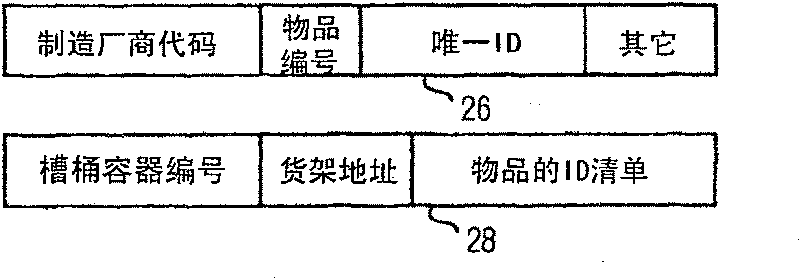
The invention provides a automated warehouse. An ID tag of an article is read when the article is loaded into a warehouse, and the ID and shelf address of the article are written into an ID tag of a bucket. A stacker crane stores the bucket (24) to the shelf address that is written in the ID tag of the bucket. Thus the article to be put into the warehouse can be easily conveyed.

Description

technical field [0001] The present invention relates to an automatic warehouse, in particular to the control of the handling device in the warehouse during storage. Background technique [0002] When goods are put into storage in an automatic warehouse, carriers such as buckets, pallets, or pallets are placed on the transport device in the warehouse such as a stacking crane, and the control unit specifies the shelves stored on the transport device. Address to make it transferable. Therefore, it is necessary to perform communication from the control unit to the conveyance device every time goods are put into storage. Although Patent Document 1 describes the idea of ​​attaching an ID tag to the tank container, it does not describe that the use of the ID tag eliminates the need for communication from the control unit to notify the transfer device of the storage location. [0003] Patent Document 1: Japanese Patent Application Publication Report, Japanese Laid-Open No. 5-81490...

Claims


Application Information

Patent Timeline
Patent Type & Authority Patents(China)
IPC IPC(8): B65G1/137G06Q10/00
CPCB65G1/1371G06Q10/08B65G1/0407B65G1/0421B65G2812/02237
Inventor 石田正人三田芳则
Owner MURATA MASCH LTD
Learn More