Method for jointing concrete between upper and lower layers of wall body in concrete

A concrete wall and lower layer technology, applied to walls, building components, buildings, etc., can solve the problems of material waste, affect the strength of the wall, increase the labor cost of wall construction, etc., to reduce material loss, improve work efficiency, and reduce labor cost effect

Inactive Publication Date: 2007-02-21
NANTONG SIJIAN CONSTR GRP
View PDF0 Cites 3 Cited by
  • Summary
  • Abstract
  • Description
  • Claims
  • Application Information

AI Technical Summary

Problems solved by technology

This will undoubtedly increase the labor cost of wall construction, and at the same time cause waste of materials due to grout leakage and m...

Method used


Image

  • Method for jointing concrete between upper and lower layers of wall body in concrete
  • Method for jointing concrete between upper and lower layers of wall body in concrete
  • Method for jointing concrete between upper and lower layers of wall body in concrete

Examples


Embodiment 1

[0017] The present embodiment is to build a plane concrete wall. The layered pouring of the concrete wall will be carried out as follows:

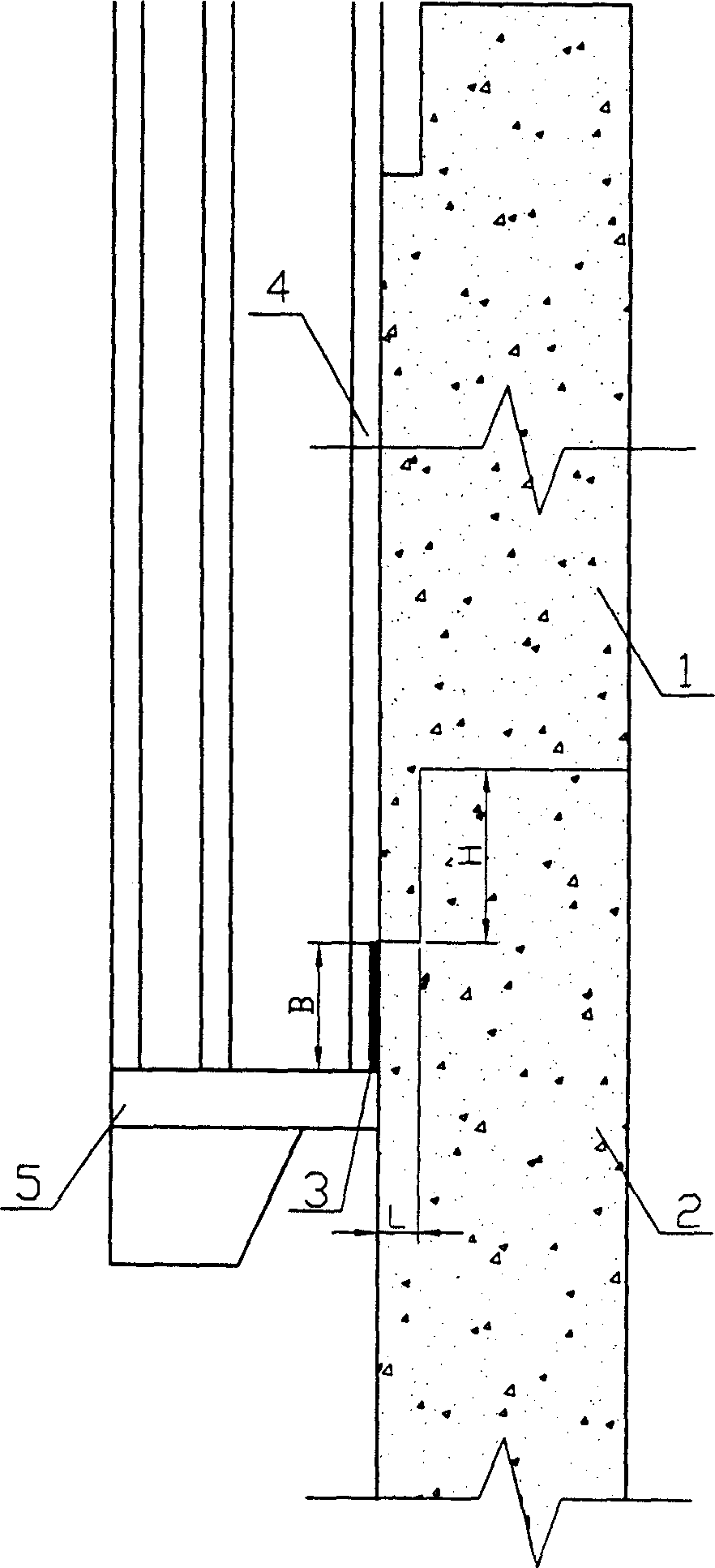
[0018] a. Except for the uppermost concrete layer of the wall, the upper end of each concrete layer is made into a rectangular gap with its outer side facing inward with a depth of L = 1.0 cm and a height of H = 20 cm through the template built. Please refer to figure 1 .

[0019] b. Paste a centimeter single-sided adhesive sponge strip with a width of B=2 along the outer edge of the above-mentioned gap.

[0020] c. Install the formwork for the upper concrete layer relative to the above concrete layer. After the installation is completed, pour concrete to form the upper concrete layer.

[0021] d. Remove the formwork of the upper concrete layer and remove all pasted single-sided adhesive sponge strips.

[0022] After repeating the above steps several times, the pouring of the wall reaches the highest layer of concrete layer. When build...

Embodiment 2

[0024] The present embodiment is to build a circular concrete wall. The layered pouring of the concrete wall will be carried out as follows:

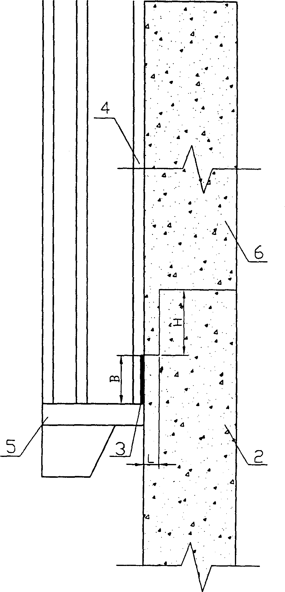
[0025] a. Except for the uppermost concrete layer of the wall, the upper end of each concrete layer is made into a rectangular gap with the outer side facing inward with a depth of L = 1.5 cm and a height of H = 30 cm through the template built. Please refer to figure 1 , the rectangular notch is essentially a circular arc surface notch with a rectangular profile.

[0026] b. Paste a centimeter single-sided adhesive sponge strip with a width of B=2 along the outer edge of the above-mentioned gap;

[0027] c. Install the upper concrete layer formwork relative to the above concrete layer, after the installation is completed, pour concrete to form the upper concrete layer;

[0028] d. Remove the formwork of the upper concrete layer and remove all pasted single-sided adhesive sponge strips.

[0029] After repeating the above steps sever...


PUM

PropertyMeasurementUnit
Heightaaaaaaaaaa
Widthaaaaaaaaaa

Abstract

The present invention relates to a method for jointing seam between upper and lower concrete layers-of concrete wall body. Said method includes the following steps: a), Except for most upper layer concrete of said wall body making one side of upper end of every layer concrete into the form of inwards-recessed rectangular notch whose depth is L cm and height is H cm; b), along the outside edge of said above-mentioned notch sticking single-side-adhesive spongs strip whose width is B cm; c), mounting relative upper layer concrete form, pouring concrete and forming relative upper concrete layer; and d), removing form and cleaning out the above-mentioned stuck single-side-adhesive sponge strip.

Description

technical field [0001] The invention relates to a method for building construction, and more specifically, relates to a method for jointing the upper and lower layers of a concrete wall. Background technique [0002] The construction of the concrete wall is generally completed by building up the formwork layer by layer and pouring layer by layer until the required height is reached. In this way, the joint at the junction of each upper and lower concrete layer can be clearly seen on the constructed concrete wall, and the upper side of the joint may still have a convex phenomenon. This is because the lower end of the upper formwork is subjected to the lateral pressure F of the concrete grout in the formwork during pouring, commonly known as "expansion", please refer to image 3 . In addition, the concrete grout in the formwork will leak out from the gap between the upper formwork and the lower concrete layer, commonly known as "slurry leakage", forming a hang G on the surface...

Claims


Application Information

Patent Timeline
IPC IPC(8): E04B2/84E04B2/00E04B1/682
Inventor 耿裕华陈健童建设花周建张赤宇张峥峰
Owner NANTONG SIJIAN CONSTR GRP
Why Eureka
Try Eureka