Liquid crystal display device repair system and method thereof

A technology for liquid crystal display devices and repair lines, which can be used in static indicators, nonlinear optics, instruments, etc., and can solve the problems of low power consumption and efficiency

Inactive Publication Date: 2007-02-21
SAMSUNG ELECTRONICS CO LTD
View PDF0 Cites 41 Cited by
  • Summary
  • Abstract
  • Description
  • Claims
  • Application Information

AI Technical Summary

Problems solved by technology

In this case, power consumption is inefficient since the op amp always consumes power regardless of whether the shorted signal line has been repaired or not

Method used


Image

  • Liquid crystal display device repair system and method thereof
  • Liquid crystal display device repair system and method thereof
  • Liquid crystal display device repair system and method thereof

Examples


Embodiment Construction

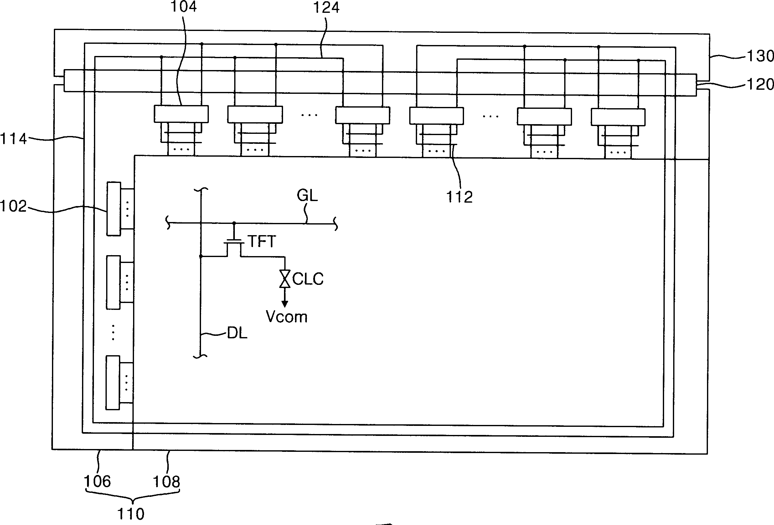
[0016] refer to figure 1 , the LCD device includes an LCD panel 110 , a data driving IC 104 for driving the data lines DL of the LCD panel 110 , and a gate driving IC 102 for driving the gate lines GL of the LCD panel 110 . The gate driving IC 102 sequentially supplies scan pulses to the gate lines GL to drive the thin film transistors TFT in response to gate control signals received from a timing controller (not shown). The data driving IC 104 converts digital video data into analog gamma voltages corresponding to gray levels.

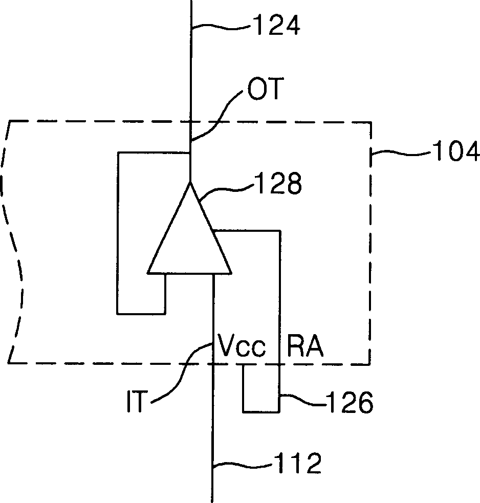
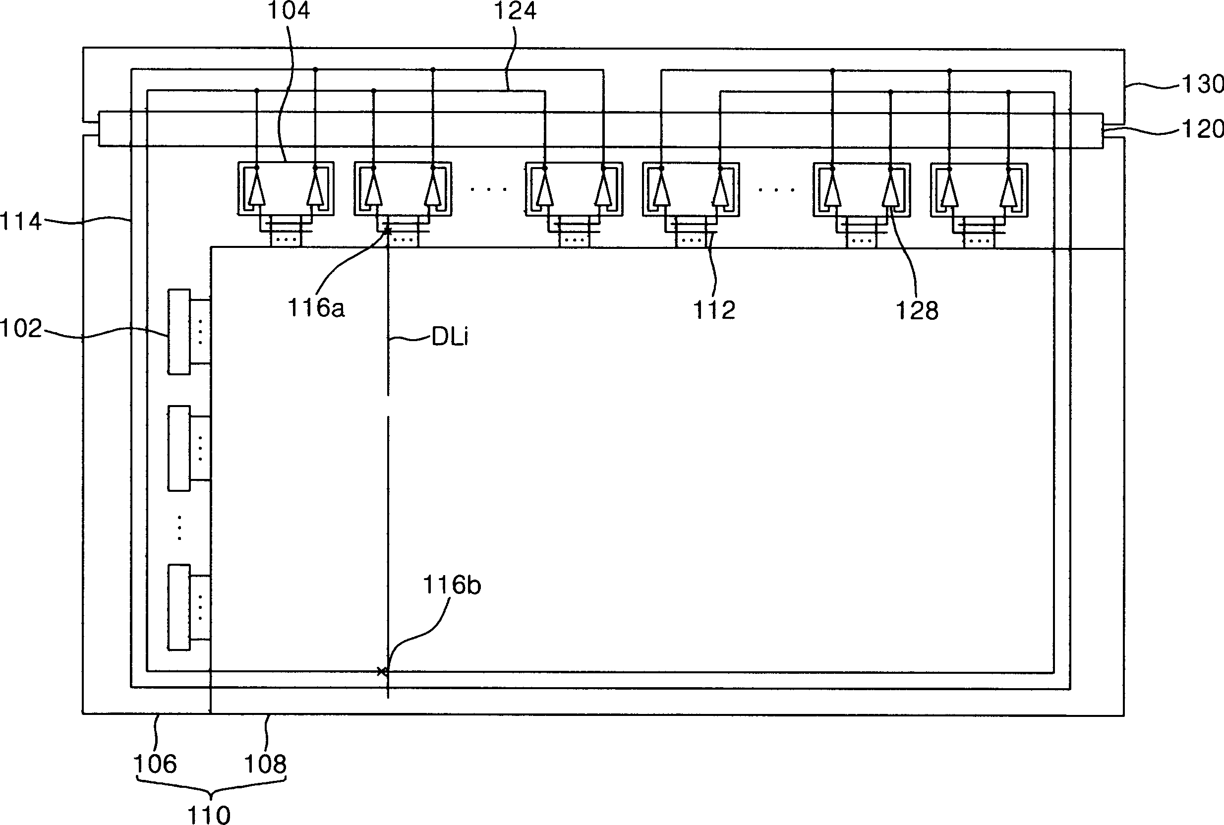
[0017] Each data driver IC consists of two such figure 2 Amplifier 128 is shown as an operational amplifier. Each operational amplifier 128 includes an input terminal IT connected to the first repair line 112 , an output terminal OT for connection to the transmission line 124 formed on the FPC 120 and the PCB 130 , and a power supply voltage terminal Vcc. The repair amplifier RA is usually connected to the terminal Vcc through a U-shaped common li...


PUM


Abstract

Disclosed are a liquid crystal display (LCD) device which can minimize power consumption and detect whether a repairing process is successful or not during a testing process, and testing and repairing methods thereof. The LCD device includes gate lines formed on a substrate, data lines formed on the substrate by crossing the gate lines, first and second repair lines for repairing at least one signal line of the data lines and gate lines, amplifiers for amplifying a driving signal supplied to the first repair line and supplying the amplified driving signal to the second repair line, and a first passing line to which input terminals of the amplifiers are commonly connected.

Description

[0001] References to related applications [0002] This application claims priority based on Korean Patent Application No. 2005-75025 filed on August 17, 2005. technical field [0003] The present invention relates to a liquid crystal display (LCD) device, and more particularly, to a low power consumption LCD device that can repair a defect and then determine whether the repair was successful. Background technique [0004] The LCD display includes a matrix of signal lines (eg, gate lines and data lines) and liquid crystal cells that display images by controlling light transmittance of liquid crystals using an electric field. The driving circuit for supplying the electric field includes a plurality of integrated circuits (ICs) for driving the gate lines and the data lines. An IC packaged on a tape carrier package (TCP) may be connected to the LCD panel by a tape automated bonding (TAB) method or may be packaged on the LCD panel by a chip on glass (COG) method. During the co...

Claims


Application Information

Patent Timeline
Patent Type & Authority Applications(China)
IPC IPC(8): G02F1/13
CPCG09G2330/08G02F1/136259G09G3/3688G09G3/006G09G2330/021G02F2001/136272G02F2001/136263G09G2300/0426G02F1/136263G02F1/136272G02F1/1345
Inventor 郭玧熙金晶日
Owner SAMSUNG ELECTRONICS CO LTD
Why Eureka
Try Eureka