
Rail comprising a rotating frame for a filtration device, and production method thereof

A technology of rotating base frame and filtering equipment, which is applied in the direction of filtration separation, separation methods, chemical instruments and methods, etc., can solve problems such as roughness, and achieve the effect of small stress and less wear

Inactive Publication Date: 2007-02-28
PRAYON TECH
View PDF3 Cites 0 Cited by
  • Summary
  • Abstract
  • Description
  • Claims
  • Application Information

AI Technical Summary

Problems solved by technology

Finally, these tracks formed by welded elements - that is to say these tracks are subjected to high stresses during their production - are not machined, so that the outer surface remains rough and present in its capacity Defect: Flatness and perfect levelness required for said unit to be supported and a surface suitable for good contact with supporting rollers

Method used


Image

  • Rail comprising a rotating frame for a filtration device, and production method thereof
  • Rail comprising a rotating frame for a filtration device, and production method thereof

Examples


Embodiment Construction

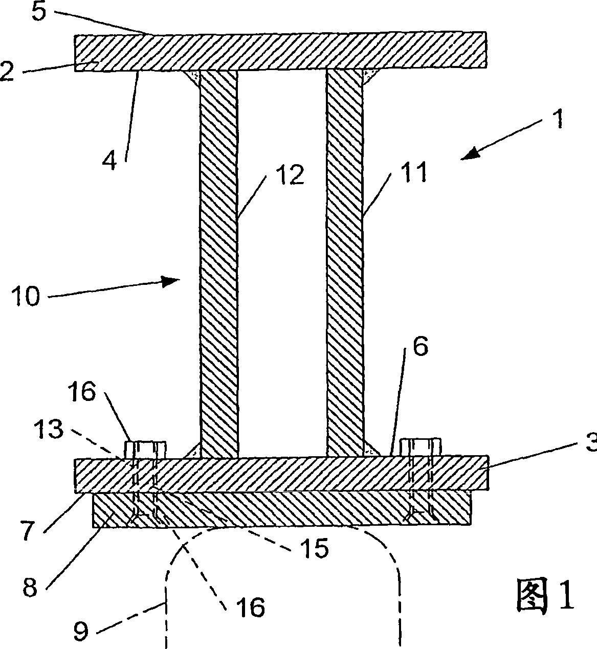
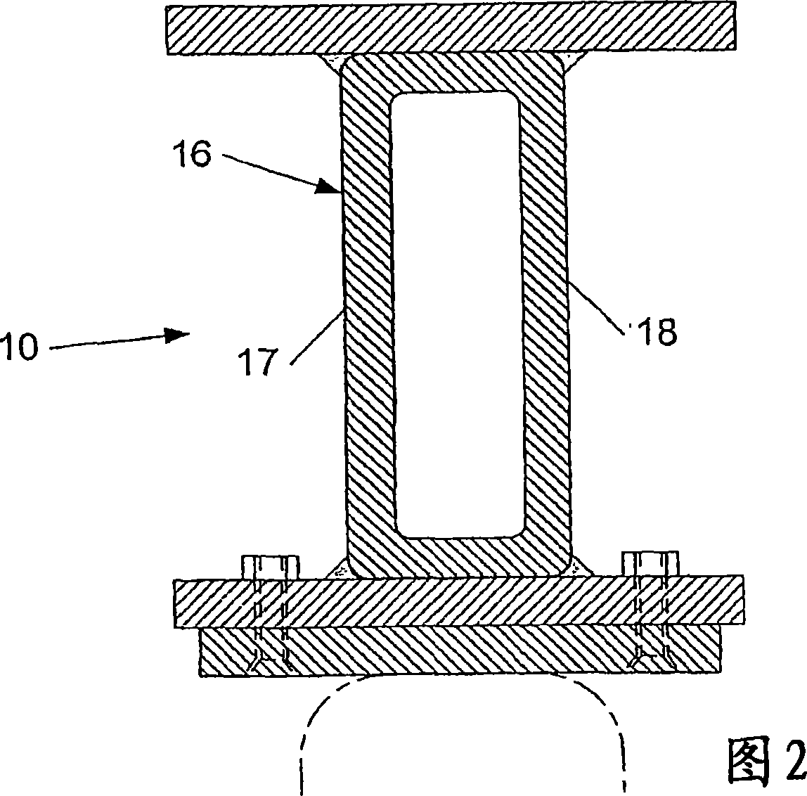
[0026] [26] In Fig. 1, a cross-section of a rail 1 of a rotating base frame of a filtering device with filtering units installed on a circulating conveying mechanism is shown. The track comprises a first flange 2 and a second flange 3 . These flanges are cut from a steel plate in sections each forming a circular or polygonal ring, the tracks thus being able to join one another to form a circle around the pivot of the endless conveyor mechanism. Complete torus or polygonal body.

[0027] [27] Said flange 2 has an inner surface 4 and an outer surface 5 for supporting at least one known, not shown filter unit, and said upper surface is supported directly or via a A structure supports the filter unit.

[0028] [28] Said flange 3 also has an inner surface 6 and an outer surface 7 . On said outer surface is fixed a wear plate 8 which is also cut from a steel plate in such a way that a segment of a circular or polygonal ring is formed. This wear plate 8 is fastened on said flange...


PUM


Abstract

The invention relates to a rail (1) comprising a rotating frame for a filtration device comprising filter cells which are disposed in the form of a carousel. The invention comprises: a first flange (2) which is cut in the shape of a circular or polygonal ring, a second flange (3) which is cut in the shape of a second circular or polygonal ring segment, a core (10) which is welded transversely to the inner surfaces (4, 6) of the flanges (2, 3) such as to form a H-shaped rail, and a wear plate (8) which is fixed to the outer surface (7) of the second flange. According to the invention, the aforementioned core (10) is formed from at least two steel crossties (11, 12) which are curved or folded parallel to on another and which are welded to the inner surfaces (4, 6) of the flanges (2, 3). Moreover, the second flange (3) and the wear plate (8) are provided with holes (13, 14) in which fixing elements (15) are disposed in order to fix the wear plate to the second flange in a detachable manner.

Description

technical field [0001] [01] The present invention relates to a track of a rotating base frame of a filtering device having a filtering unit, said filtering device being mounted on a circulating conveying mechanism, said track comprising: [0002] [02] A first flange cut from a steel plate to form a first annular segment or polygonal segment and having an outer surface and an inner surface for contact with At least one filter unit fits, [0003] [03] - a second flange cut from a steel plate in such a way as to form a second annular segment or polygonal segment, and having an outer surface and an inner surface, [0004] [04] - a steel web welded transversely to the inner surfaces of said first and second flanges to form a track, the track generally being H-shaped in cross-section, and [0005] [05] - A wear plate cut from a steel plate to form a third annular or polygonal segment and fixed to the outer surface of said second flange to form contact with the support roller a su...

Claims


Application Information

Patent Timeline
Patent Type & Authority Applications(China)
IPC IPC(8): B01D33/19
CPCB01D33/19B01D35/00
Inventor S·库罗夫斯基
Owner PRAYON TECH
Learn More