
Cotton conditioner for a cotton harvester

A regulator and cotton technology, applied in the field of structure, can solve the problems of reducing the ability to contact and remove fibers, affecting separation efficiency, etc.

Active Publication Date: 2007-03-07
DEERE & CO
View PDF0 Cites 5 Cited by
  • Summary
  • Abstract
  • Description
  • Claims
  • Application Information

AI Technical Summary

Problems solved by technology

Fiber orientation also affects separation efficiency, if the fibers are not exposed satisfactorily, then the ability of the harvesting mechanism to reach and remove the fibers is reduced

Method used


Image

  • Cotton conditioner for a cotton harvester
  • Cotton conditioner for a cotton harvester
  • Cotton conditioner for a cotton harvester

Examples


Embodiment Construction

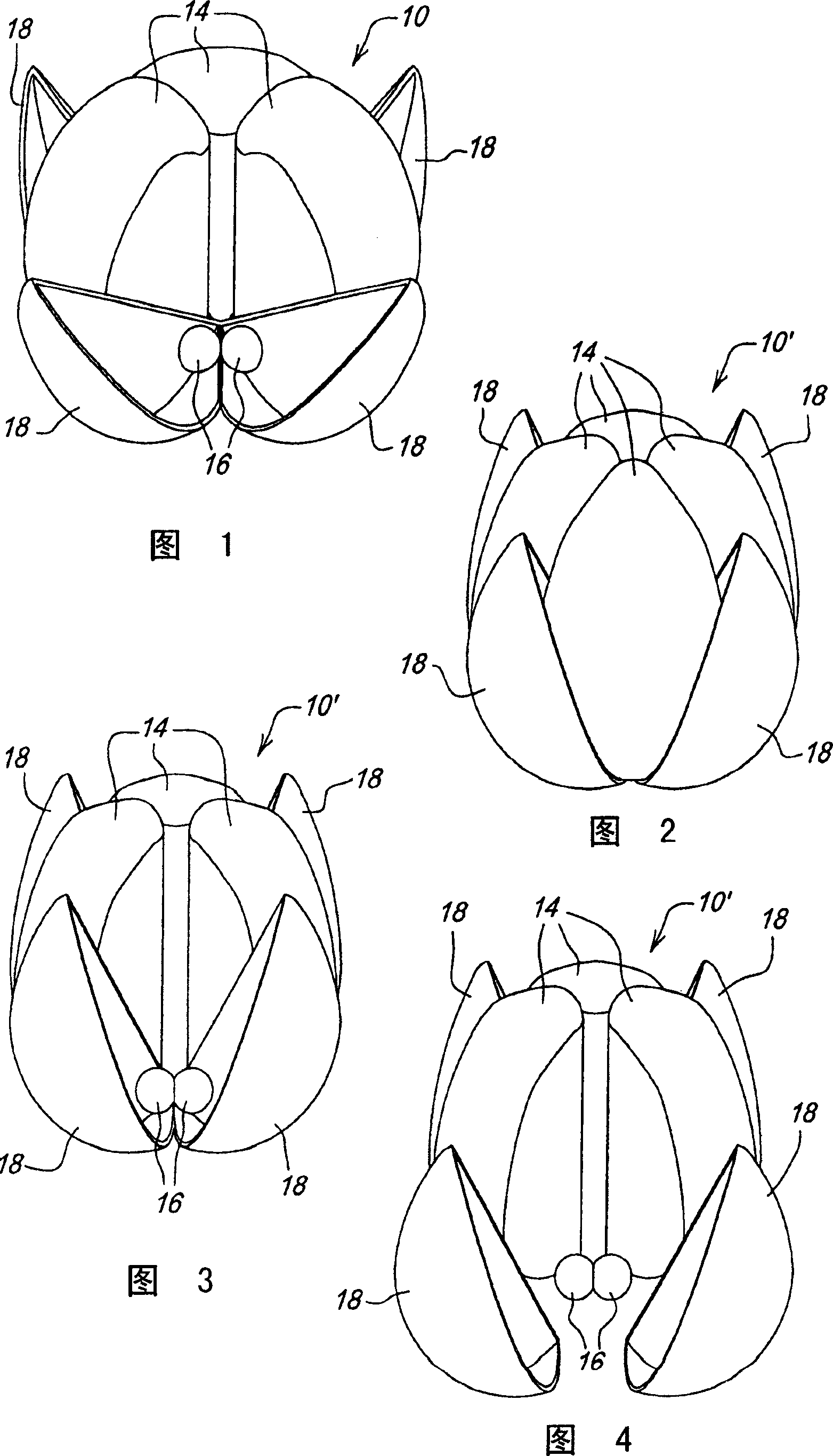
[0018] Referring now to Figure 1 , there is shown a cotton boll 10 from a cotton plant 12 . Cotton bolls 10 contain four groups or tufts 14 of cotton fibers attached to cotton seeds 16 . For the sake of clarity, one of the clusters 14 is removed in FIG. 1 . Tufts 14 are typically contained within burrs 18 when the cotton plant matures. As shown in accompanying drawing 1, when plant matures, burr 18 opens and exposes cotton fiber. However, there are still a large number of bolls that are not fully opened as shown in the accompanying drawings 2 and 3 of the cotton bolls 10'. The fiber on the partially opened boll 10' is not fully exposed, and the cottonseed 16 is still tightly wrapped.

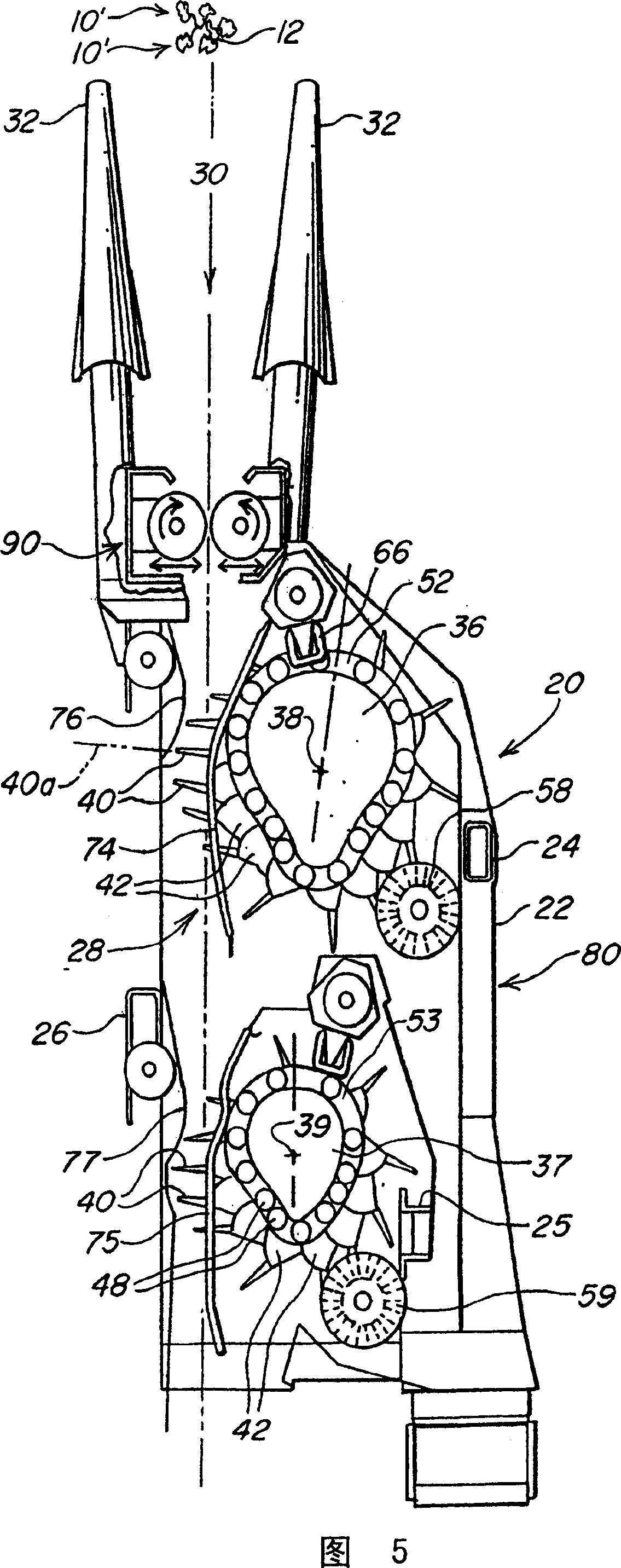
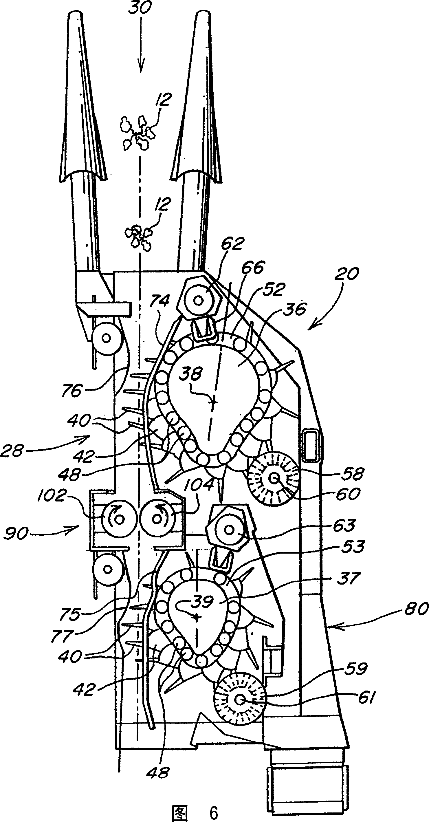
[0019] Referring now to accompanying drawing 5 accompanying drawing 6, wherein shows the row device 20 that cotton picking machine is useful. The row unit 10 has a shroud 22 with vertical members as shown at positions 24,25,26. A fore-and-aft extending row receiving area 20 is defined which...


PUM


Abstract

A conditioning mechanism is placed forwardly of the cotton harvesting mechanism on a cotton harvester. Opposing elements compress portions of the cotton plant to compress the cotton bolls and deform the cotton boll hulls. The deformation loosens the cotton fiber relative to the hulls to improve the ability of the harvesting mechanism to harvest the seed and fiber. In one embodiment, differential surface velocity of the opposing elements improves boll opening and fiber orientation for more effective spindle contact.

Description

technical field [0001] This invention relates generally to cotton harvesters and, more precisely, to a structure which enhances the performance of cotton harvester apparatus for harvesting cotton fibers and cotton seeds from cotton plants. Background technique [0002] Cotton fibers are contained within cotton bolls, and each fiber is attached to one of several seeds in the boll, which opens to expose the fibers as the boll matures. The seeds are retained in the cavity formed by the opened boll or husk. [0003] Various types of cotton harvesting equipment include mechanisms for contacting and extracting the cotton seeds and cotton fibers from the cotton plants. Harvesting efficiency depends on the ability of the mechanism to remove the seeds and fibers from the opened bolls, which, in turn, depends on the degree to which the seeds and fibers are attached to the cotton bolls. Harvesting efficiency is greatly reduced if the fibers and seeds are tightly b...

Claims


Application Information

Patent Timeline
Patent Type & Authority Applications(China)
IPC IPC(8): A01D46/14A01D46/08D01B1/02D01G99/00
CPCA01D46/08
Inventor J·R·福克斯M·S·菲利普斯
Owner DEERE & CO
Learn More