Test tube rack

A technology for test tube racks and test tubes, which is applied in the field of test tube racks for hematology analyzers. It can solve the problems of inability to turn over and upside down, damage to test tubes, and inability to mix the test tubes, and achieve the effect of simple structure.

Active Publication Date: 2007-03-07
TECOM SCI CORP
View PDF1 Cites 12 Cited by
  • Summary
  • Abstract
  • Description
  • Claims
  • Application Information

AI Technical Summary

Problems solved by technology

[0002] At present, the test tube rack used by the hematology analyzer for automatic sample delivery is a common test tube rack commonly used in the market. The test tubes placed in the test tube rack usually cannot be clamped, and often shake during the automatic sample delivery process, and cannot be turned upside down. It is difficult to complete the functions of mixing and puncturing in the test tube rack, and its volume is large. The above defects have been difficult to meet the diversified design requirements of automatic sample delivery.
[0003] In the existing technology, there are also some new test tube racks that can prevent overturning. For example, the utility model patent with the notification number CN2354657 discloses a multi-tooth sliding and fixed test tube rack. In the case of manual operation, the test tube will not fall, and the fixing rod is directly applied to the test tube, which is easy to cause damage to the test tube
The utility model patent with the notification number CN2589067 discloses a porous test tube rack. Its structure can turn the test tube rack without manual operation and the test tube will not fall, and it is not easy to cause damage to the test tube, but the test tube cannot be alone in the test tube rack. Rapid eccentric mixing and rotation cannot meet the function of mixing the test tube without detaching from the test tube rack

Method used


Image

  • Test tube rack
  • Test tube rack

Examples


Embodiment

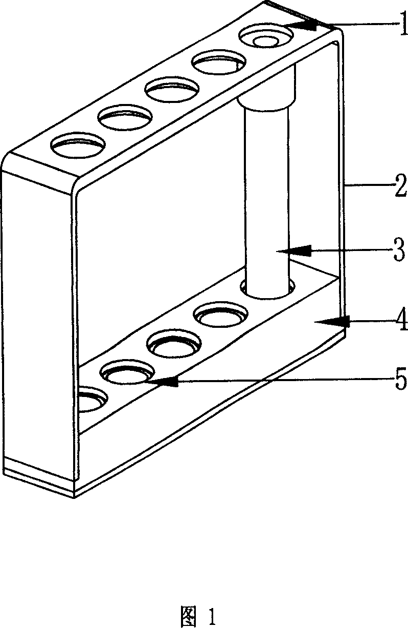
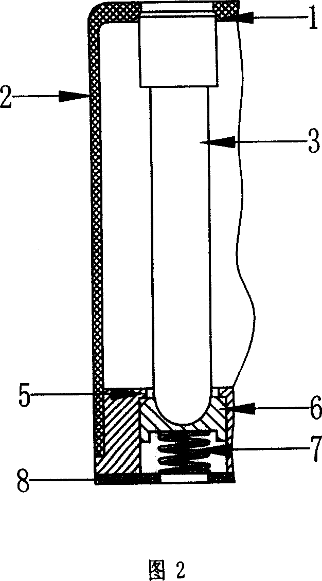
[0021] Accompanying drawing 1, accompanying drawing 2 are the structural representations of this embodiment.

[0022] This embodiment is made up of test tube frame (2), test tube support seat (4), test tube frame bottom plate (8), test tube support seat (4) is located at the bottom of test tube frame (2), is connected with test tube frame bottom plate (8) , the test tube frame (2) and the test tube frame bottom plate (8) constitute the outer frame of the test tube rack, and the top of the test tube frame (2) is provided with 5 positioning holes (1) for positioning the counterbore structure of the test tube, and the test tube support seat ( 4) is also correspondingly provided with 5 guide holes (5) with a counterbore structure, and a guide post (6) and a spring (7) are built in each guide hole.

[0023] The test tube (3) is placed in the guide hole (5) on the test tube support seat (4) from the side of the test tube rack, and the test tube (3) is pressed upward on the test tube...


PUM


Abstract

The invention relates to a tube support, which comprises tube frame (2), tube base (4), and tube frame bottom plate (8). Wherein, the tube base (4) is at the bottom of tube frame (2) to connect the tube frame bottom plate (8); the tube frame (2) and tube frame bottom plate 98) form the frame of tube support; the invention is characterized in that the upper part of tube frame (2) has a group of tube positioning holes (1); the tube base (4) relative to the positioning hole (1) has tube guide hole (5); the guide hole contains guide post (6), spring (7). The invention has simple structure, while it can be arranged freely, and it can rotate uniformly eccentrically via external force.

Description

technical field [0001] The invention relates to a test tube rack, in particular to a blood cell analyzer test tube rack. Background technique [0002] At present, the test tube rack used by the hematology analyzer for automatic sample delivery is a common test tube rack commonly used in the market. The test tubes placed in the test tube rack usually cannot be clamped, and often shake during the automatic sample delivery process, and cannot be turned upside down. It is difficult to complete the functions of mixing and puncturing in the test tube rack, and its volume is large. The above defects have been difficult to meet the diversified design requirements of automatic sample delivery. [0003] In the existing technology, there are also some new test tube racks that can prevent overturning. For example, the utility model patent with the notification number CN2354657 discloses a multi-tooth sliding and fixed test tube rack. Carry out under the situation of manual assistance o...

Claims


Application Information

Patent Timeline
Patent Type & Authority Applications(China)
IPC IPC(8): B01L9/06
Inventor 戴洪卢伟江朱敏生程伟龙俞文
Owner TECOM SCI CORP
Why Eureka
Try Eureka