Electric motor using armature

A motor and armature technology, applied in the direction of electric components, electrical components, electromechanical devices, etc., can solve the problems of reduced reliability of the motor, adverse consequences, insufficient bonding force of the slot wedge 23, etc.

Inactive Publication Date: 2007-03-07
LG ELECTRONICS (TIANJIN) APPLIANCES CO LTD
View PDF0 Cites 10 Cited by
  • Summary
  • Abstract
  • Description
  • Claims
  • Application Information

AI Technical Summary

Problems solved by technology

However, the above method will lead to a decrease in the reliability of the motor and the problem of an increase in cost
[0009] In addition, because the bonding force of the slot

Method used


Image

  • Electric motor using armature
  • Electric motor using armature
  • Electric motor using armature

Examples


Embodiment Construction

[0031] For convenience of description, the same reference numerals will continue to be used for the same or equivalent parts as those described or illustrated above.

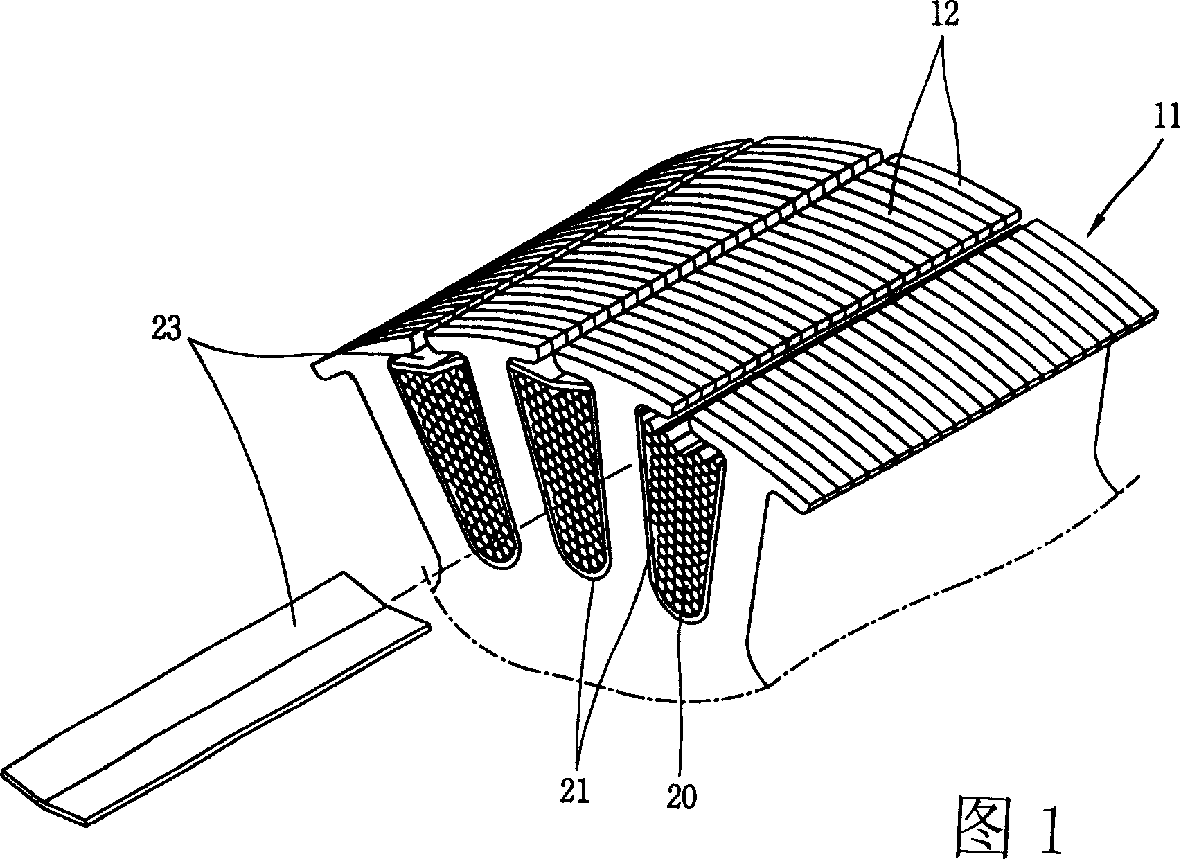
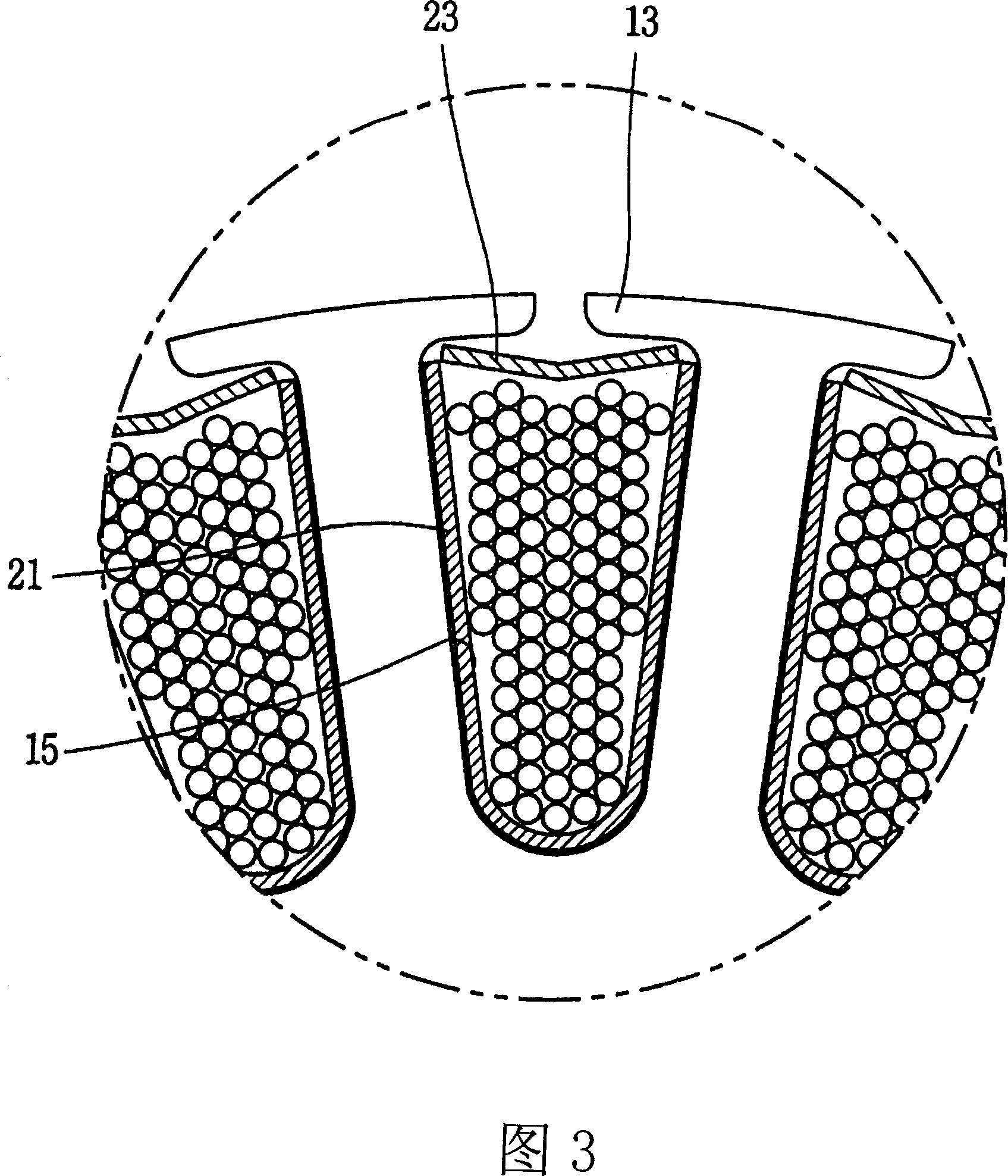
[0032] As shown in Figures 4 and 5, the motor armature 30 of the present invention includes the following parts: a magnetic core 11 having a plurality of slots 15 opening outward; a coil 20 wound inside the slots 15; Insulator, and when projected on a plane, it has a length extending from one side of the opening of the slot 15 along the inner wall to the other side, and then plays the role of insulating the slot insulating paper 31 between the magnetic core 11 and the coil 20 .

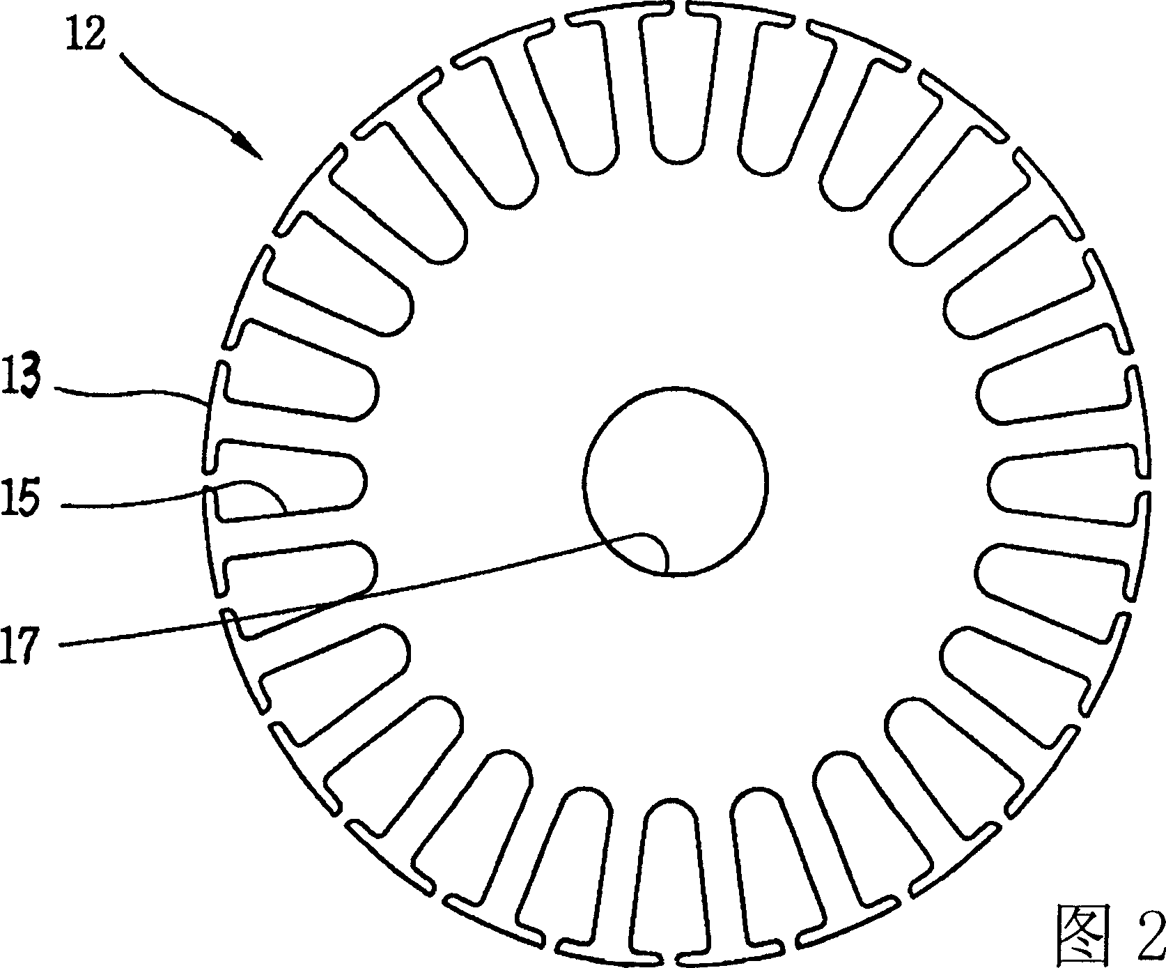
[0033] The magnetic core 11 is composed of a plurality of disk-shaped motor steel sheets 12 laminated insulatedly along the thickness direction. A shaft hole 17 capable of accommodating and connecting a rotating shaft is formed at the center of each motor steel plate 12 . The periphery of each motor steel plate 12 is formed with the f...


PUM


Abstract

This invention relates to motor armature, which comprises the following parts: magnetic core formed by several motor steel board with several raw gear along radium direction; one side open along radium direction between adjacent raw; tank insulation paper with one side along inner wall to other side when in plane projection; tank weld to block tank open formed by insulator; central bending curve relative to tank shape to above magnetic core formed along magnetic core.

Description

technical field [0001] The invention relates to an armature for a motor. Background technique [0002] As we all know, a motor is a device that converts electrical energy into mechanical energy. Here, the armature is a part that interrupts a magnetic flux formed by a magnetic pole (field), and moves relative to a magnetic field together with the magnetic pole, thereby converting electrical energy into mechanical energy. [0003] Generally, the above-mentioned armature performs rotational motion around a rotating shaft in electric motors such as DC motors. In addition, the above-mentioned armature generally includes the following parts: a magnetic core formed by insulated and laminated motor steel sheets having a plurality of slots opening radially outward; and a coil wound around the slots. [0004] As shown in Figures 1, 2, and 3, the armature for a motor consists of the following parts: a magnetic core 11 formed by insulated lamination of motor steel plates 12 with sawto...

Claims


Application Information

Patent Timeline
IPC IPC(8): H02K1/26H02K3/12H02K3/34H02K3/487
Inventor 金政勋
Owner LG ELECTRONICS (TIANJIN) APPLIANCES CO LTD
Why Eureka
Try Eureka