Control device for geometric proportion driven power supplying apparatus

A power supply and control device technology, applied in output power conversion devices, control/regulation systems, instruments, etc., can solve problems such as inability to achieve control and protection

Inactive Publication Date: 2007-03-07
SYST GEN
View PDF0 Cites 6 Cited by
  • Summary
  • Abstract
  • Description
  • Claims
  • Application Information

AI Technical Summary

Problems solved by technology

Therefore, the control and protection of each phase (cycle-by-cycle) cannot be achieved

Method used


Image

  • Control device for geometric proportion driven power supplying apparatus
  • Control device for geometric proportion driven power supplying apparatus
  • Control device for geometric proportion driven power supplying apparatus

Examples


Embodiment Construction

[0078] In order to further explain the technical means and effects adopted by the present invention to achieve the intended purpose of the invention, the specific implementation manner, Structure, characteristic and effect thereof are as follows in detail.

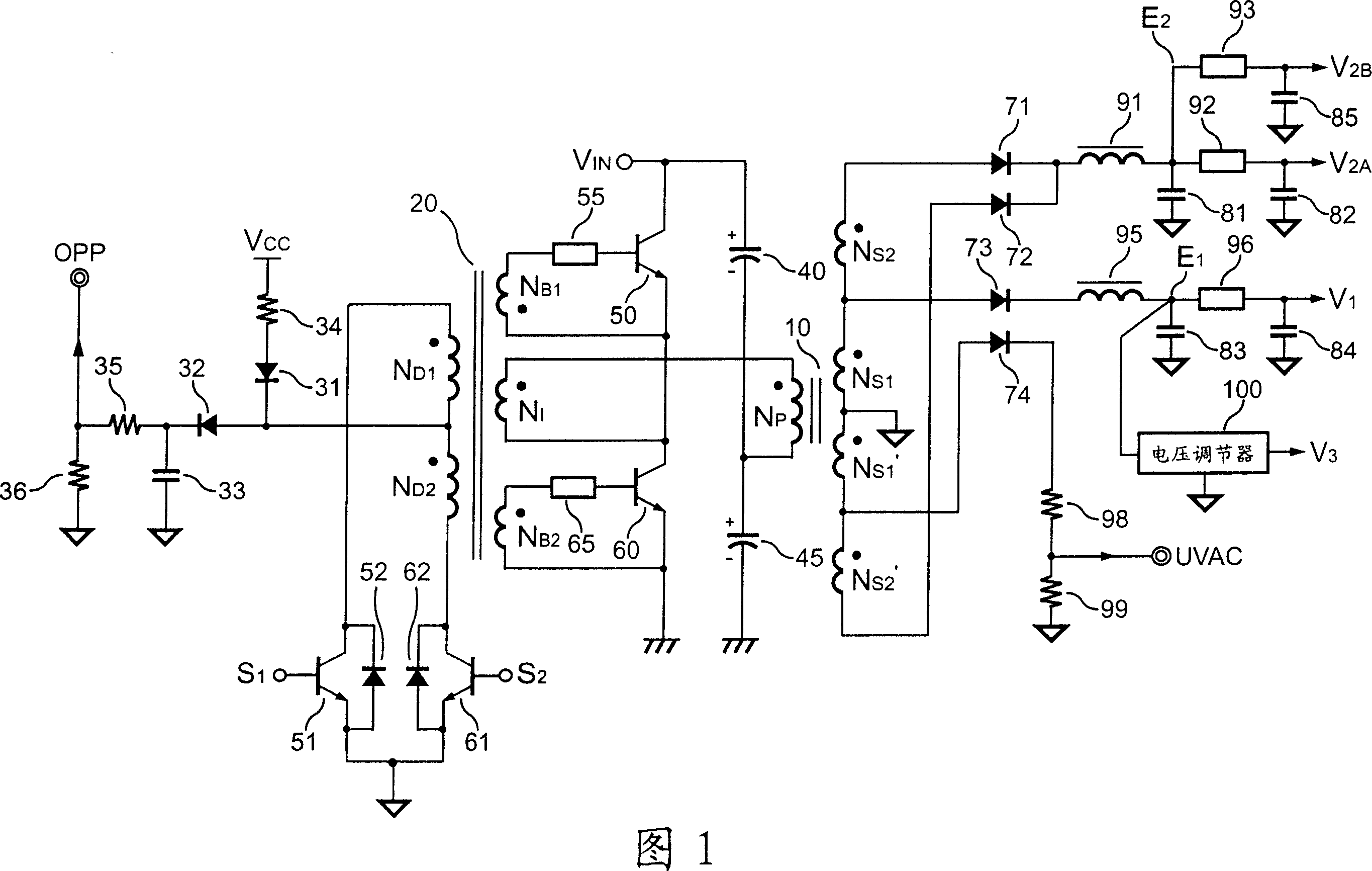
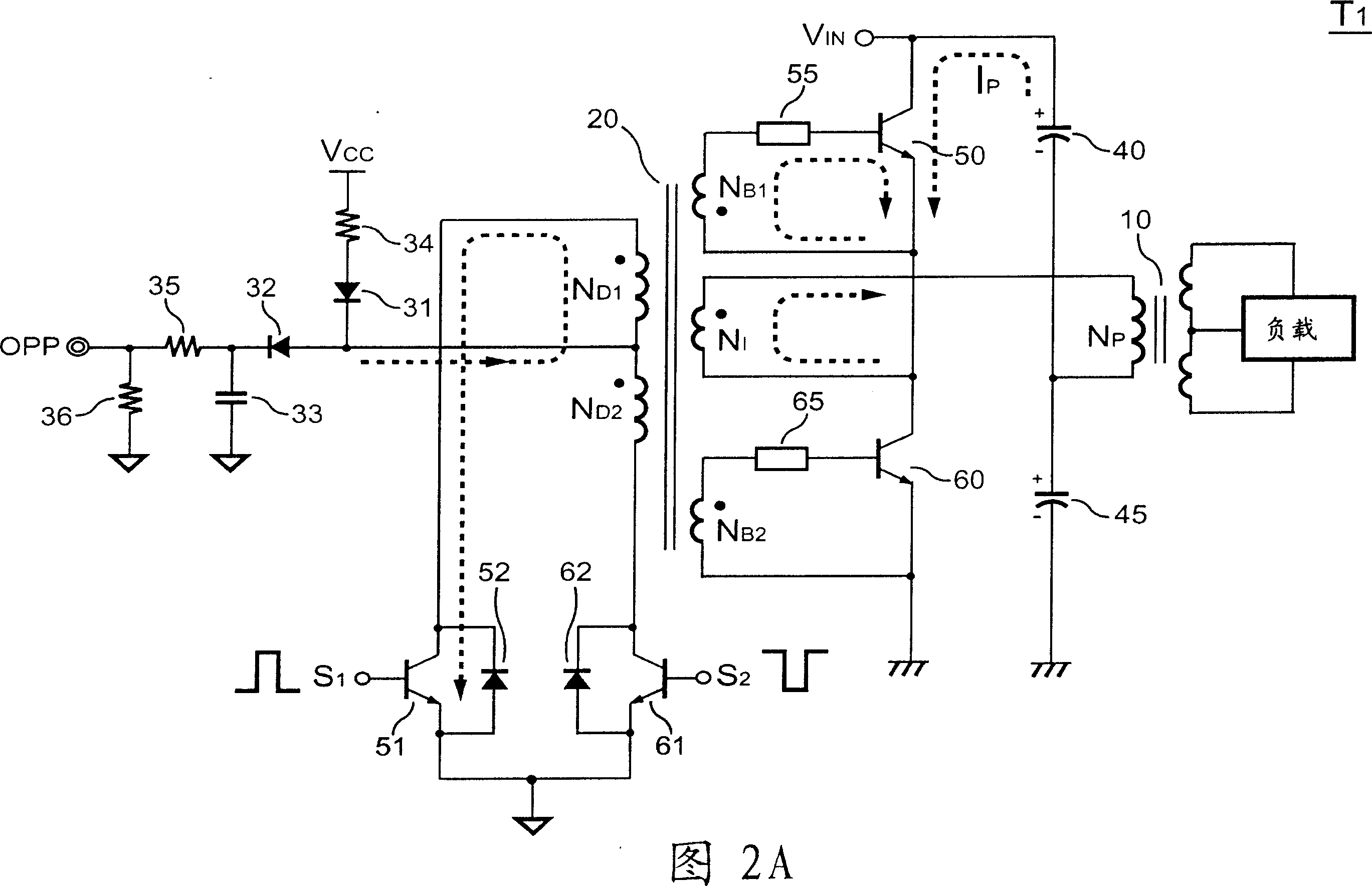
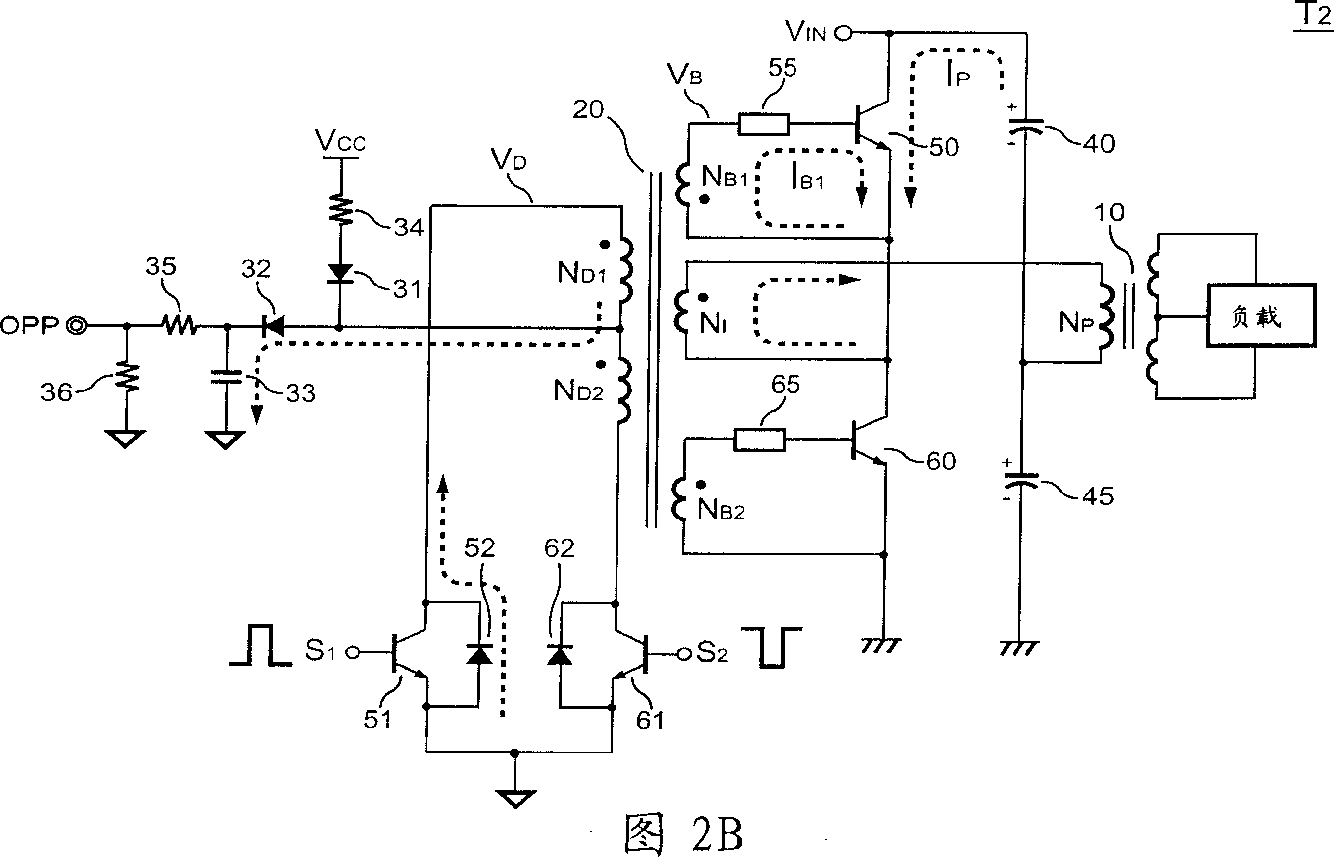
[0079] To facilitate the description of the application of the present invention, the following embodiments still use the proportional driving power supply in FIG. 1 as the control target of the control device in the embodiments of the present invention. Those skilled in the art can uphold the spirit of the present invention and the teachings of the following embodiments, and deduce it to other power supplies by analogy.

[0080] FIG. 3 illustrates an embodiment of a control device of a proportional driving power supply according to the present invention. Please refer to FIG. 3 , the control device of the ratio-driven power supply (hereinafter referred to as the power supply) includes a first feedback input terminal IN, a...


PUM


Abstract

This invention relates to control device about one equal drive power supplier, which comprises one feedback control circuit to supply power and flexible input end is used to set flexible start time of power supplier with first and second output ends are used to output first and second signals to couple power supplier one first switch and second switch to control power supplier output with one protection unit composed of voltage input end, current detection end and power detection end and signal detection end.

Description

technical field [0001] The invention relates to a control device of a power supply, in particular to a control device of an proportional driving power supply. Background technique [0002] The advantage of the proportional driving power supply circuit is high efficiency, especially when driving a bipolar transistor, its control device does not need to generate a large base current to drive the bipolar transistor. The control device only needs to generate a small control signal to drive and control a high-watt power output. [0003] Figure 1 is a circuit of a ratio-driven power supply. A first output signal S generated by the control device (not shown in the figure) 1 and a second output signal S 2 , are used to control the driving transistors 51 and 61 respectively. The driving transistors 51 and 61 are connected to a driving transformer 20 to control switching of the power transistors 50 and 60 . The power transistors 50 , 60 and the capacitors 40 , 45 form a half-brid...

Claims


Application Information

Patent Timeline
Patent Type & Authority Applications(China)
IPC IPC(8): H02M7/48H02M7/537H02M7/538H02M5/22H02M5/293G05F1/46
Inventor 杨大勇薛正祺吕瑞鸿王周昇
Owner SYST GEN
Why Eureka
Try Eureka