Standing-wave ratio detecting method and device

A standing wave ratio detection and standing wave ratio technology, applied in the field of communication, can solve the problem of high implementation cost, and achieve the effects of low cost, simple circuit and reduced single board area

Active Publication Date: 2007-03-07
XFUSION DIGITAL TECH CO LTD
View PDF0 Cites 35 Cited by
  • Summary
  • Abstract
  • Description
  • Claims
  • Application Information

AI Technical Summary

Problems solved by technology

[0006] The purpose of the present invention is to provide a standing wave ratio detection method and device to solve the problem of high implementation cost caused by the use of analog-to-digital conversion chips for power detection in the above-mentioned related technologies

Method used


Image

  • Standing-wave ratio detecting method and device
  • Standing-wave ratio detecting method and device
  • Standing-wave ratio detecting method and device

Examples


Embodiment Construction

[0029] Preferred embodiments of the present invention will be specifically described below with reference to the accompanying drawings, wherein the accompanying drawings constitute a part of the application and are used together with the embodiments of the present invention to explain the principle of the present invention.

[0030] The invention provides a standing wave ratio detection method and device.

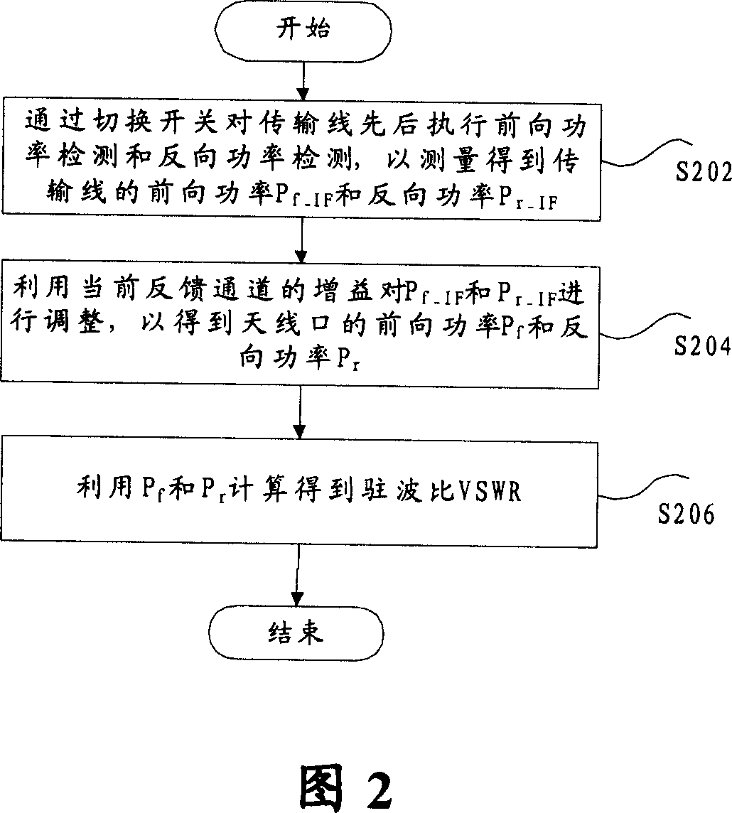
[0031] Fig. 2 has shown the standing wave ratio detection method according to the present invention, and it comprises the following steps:

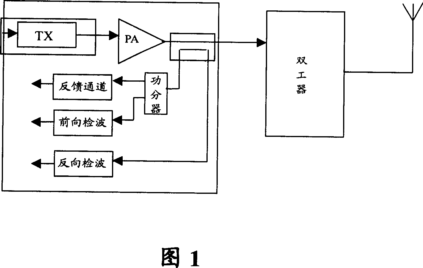
[0032] Step S202: Perform forward power detection and reverse power detection on the transmission line successively by switching the switch to measure the forward power P of the transmission line f_IF and reverse power P r_IF ;

[0033] Step S204: Use the gain of the current feedback channel to P f_IF and P r_IF Adjust to get the forward power P of the antenna port f and reverse power P r ;as well as

[0034] Step S206: Using P ...


PUM


Abstract

This invention provides one standing wave ratio test method, which comprises the following steps: a, executing front power test and back test through switch on transmission line to get transmission line front power P and back power P; b, using current feedback channel gains to adjust P and P to get antenna front power and back power; c, using P and P to compute standing wave ratio VSWR. This invention also provides one stand wave ratio test device.

Description

technical field [0001] The present invention relates to the communication field, in particular to a standing wave ratio detection method and device. Background technique [0002] The base station VSWR (Voltage Standing Wave Ratio, standing wave ratio) is an important parameter of the radio frequency, wherein the standing wave is caused by impedance mismatch on the transmission line. When the impedance on the transmission line does not match, a part of the signal power will be reflected back. Through a directional coupler, the forward power and reverse power in the reflected signal power can be detected respectively. The worse standing wave ratio means that the signal reflection is more severe, which means that the matching effect between the load and the transmission line is relatively poor. Therefore, in a system, if the VSWR is poor, the signal transmission effect may be deteriorated, and the channel gain may decrease. A typical example is the problem of decreased sensiti...

Claims


Application Information

Patent Timeline
Patent Type & Authority Applications(China)
IPC IPC(8): H04B3/46H04B3/04
CPCG01R27/06
Inventor 范钦槐
Owner XFUSION DIGITAL TECH CO LTD
Why Eureka
Try Eureka