Method, device for producing elemental image array for three-dimensional image display
一种三维图像、显示设备的技术,应用在图像通信、图像数据处理、电气元件等方向,能够解决离散、不清楚位置是否为最佳位置等问题
- Summary
- Abstract
- Description
- Claims
- Application Information
AI Technical Summary
Problems solved by technology
Method used
Image
Examples
no. 1 example
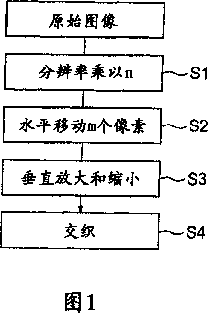
[0038] 1 to 4, a method of generating an elemental image array for three-dimensional image display according to a first embodiment of the present invention will be described.
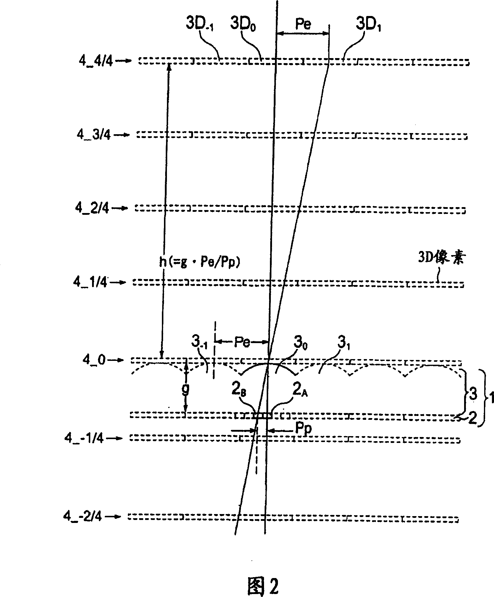
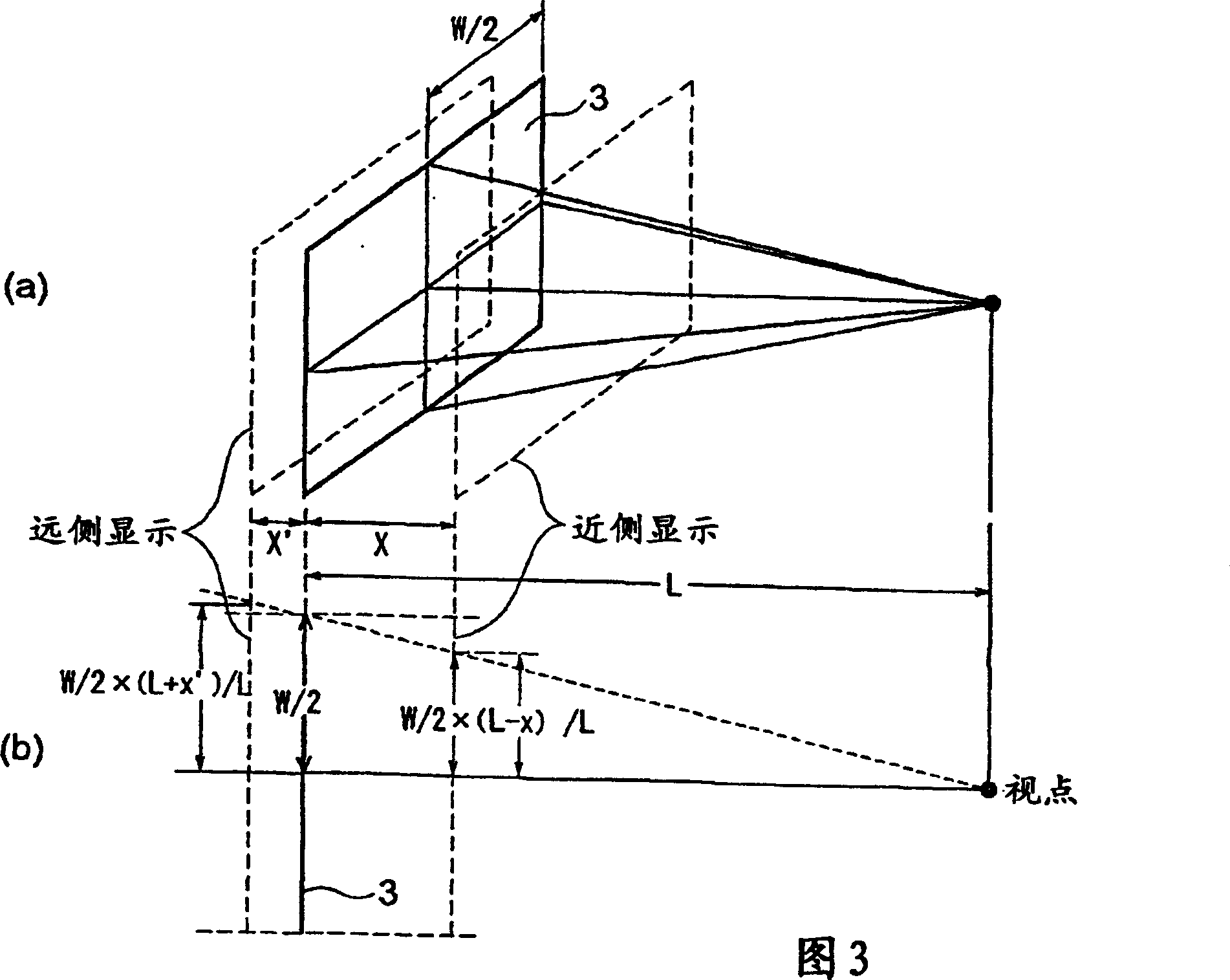
[0039] First, the principle of the method for generating an elemental image array for three-dimensional image display of this embodiment will be described with reference to FIGS. 2 to 4(b).
[0040]The generation method of this embodiment is implemented in a horizontal parallax type three-dimensional image display device. Fig. 2 is a horizontal cross-sectional view of the horizontal parallax three-dimensional image display device. The horizontal parallax three-dimensional image display device 1 includes, for example, a two-dimensional image display device 2 constituted by a liquid crystal panel, and a light control unit 3 constituted by, for example, a lenticular sheet having an exit pupil. The two-dimensional image display device 2 has pixels arranged two-dimensionally, and each pixel has a different ...
no. 2 example
[0066] An elemental image array generating apparatus for three-dimensional image display according to a second embodiment of the present invention will now be described with reference to FIGS. 6 to 16 . The element image array generating apparatus for three-dimensional image display according to this embodiment is an apparatus in which the element image array generating method for three-dimensional image display according to the first embodiment of the present invention is implemented. Figure 6 shows the structure of the device. The element image array generation device of this embodiment includes an image processing unit 20 , an image information rearrangement processing unit 22 , an element image array interleave processing unit 24 , a viewpoint image generation processing unit 26 , a viewpoint image interleave unit 28 , and a rearrangement processing unit 30 .
[0067] The display area of the original image to be displayed as a two-dimensional image (as indicated by the s...
no. 3 example
[0082] Referring now to FIGS. 17 and 18, a procedure for generating an element image array for three-dimensional image display according to a third embodiment of the present invention will be described. The generation program of this embodiment is a program that realizes the element image array generation method for three-dimensional image display according to the first embodiment. 17 and 18 are perspective and block diagrams showing an example of a computer system 130 that executes the generating program of this embodiment.
[0083] In FIG. 17, a computer system 130 includes a computer main body 131 having a CPU, a display device 132 such as a CRT, an input unit 133 such as a keyboard and a mouse, and a printer 134 for printing.
[0084] As shown in FIG. 18 , the computer main body 131 has a built-in memory 135 configuring a RAM, and a storage unit 136 may be provided inside or outside the main body 131 . The storage unit 136 includes a floppy disk (FD) drive 137 , a CD-ROM ...
PUM
 Abstract
Description
Claims
Application Information
 - R&D
- Intellectual Property
- Life Sciences
- Materials
- Tech Scout
- Unparalleled Data Quality
- Higher Quality Content
- 60% Fewer Hallucinations
Browse by: Latest US Patents, China's latest patents, Technical Efficacy Thesaurus, Application Domain, Technology Topic, Popular Technical Reports.
© 2025 PatSnap. All rights reserved.Legal|Privacy policy|Modern Slavery Act Transparency Statement|Sitemap|About US| Contact US: help@patsnap.com


