Axial piston machine

A technology of axial pistons and machines, which is applied in the direction of machines/engines, mechanical equipment, liquid variable capacity machines, etc., can solve the problems of pressure and complex design of tank channels, etc., and achieve easy pipeline laying, low cost, and reduced noise emission Effect

Inactive Publication Date: 2007-03-07
BOSCH REXROTH AG
View PDF1 Cites 16 Cited by
  • Summary
  • Abstract
  • Description
  • Claims
  • Application Information

AI Technical Summary

Problems solved by technology

Another disadvantage of the known solution is that the pressure supply via two external control panels requires a relatively complex design of the pressure and tank channels

Method used


Image

  • Axial piston machine
  • Axial piston machine
  • Axial piston machine

Examples


Embodiment Construction

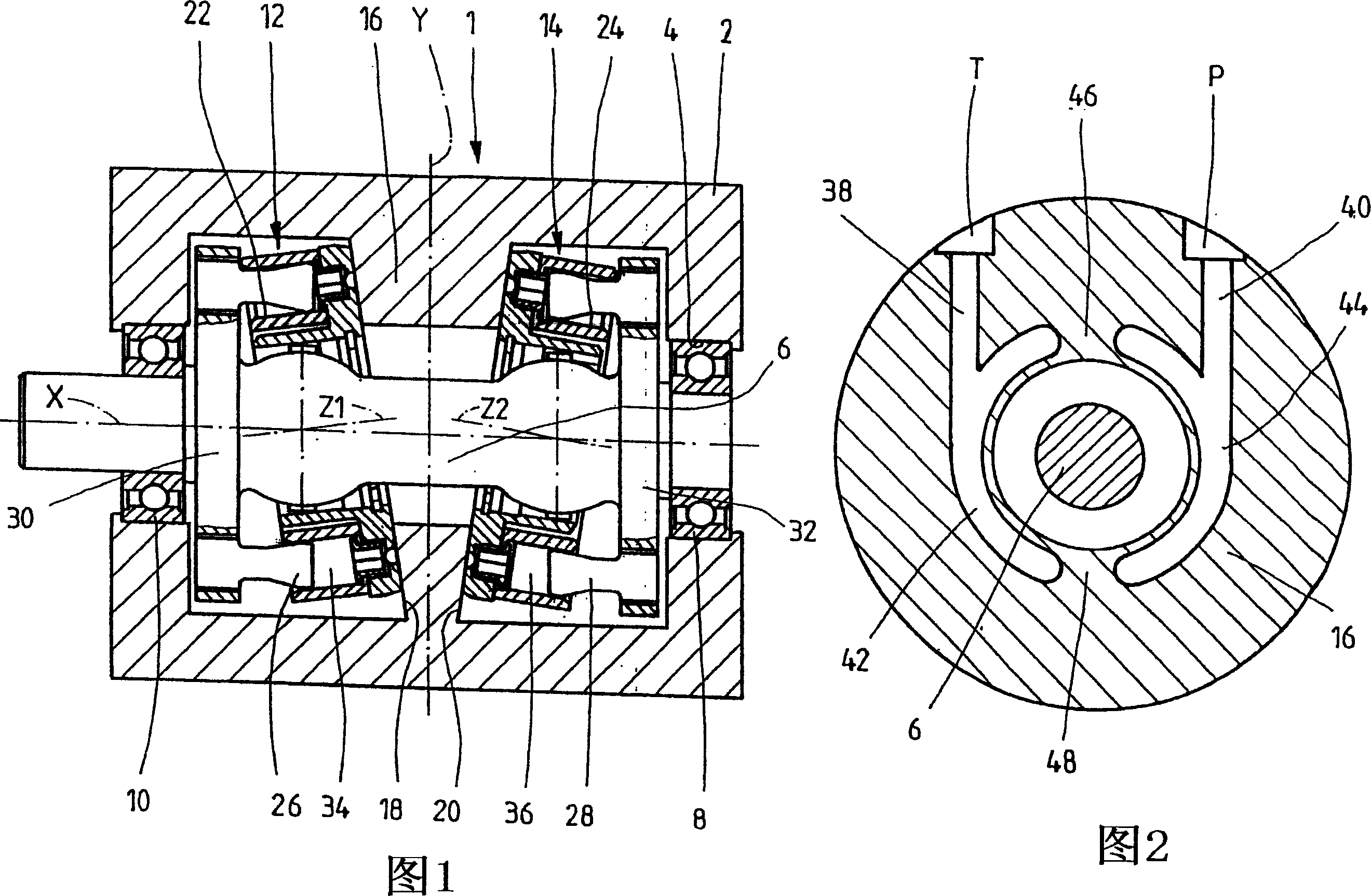
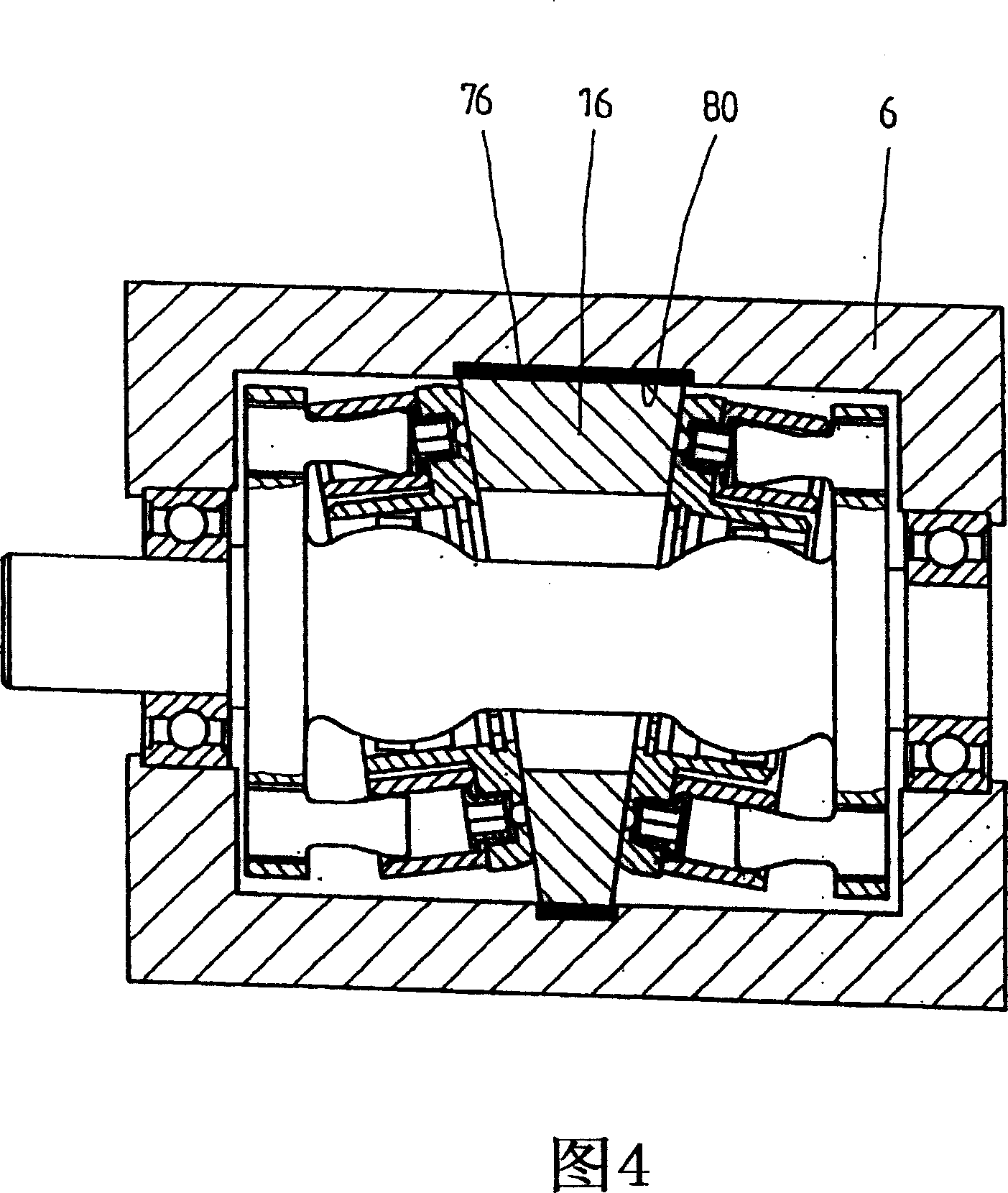
[0019] In FIG. 1 , a simplified longitudinal section through an axial piston machine 1 , such as a hydraulic pump, is shown. FIG. 2 shows a geometrically imprecise schematic cross-section along the vertical dotted line y in FIG. 1 . The axial piston machine 1 thus has a housing 2 in which an axial bore 4 is formed. In this shaft bore, the shaft 6 is supported by two bearings 8 , 10 . Said shaft 6 (drive shaft in the case of the pump) supports two cylinder barrels 12 , 14 , the axes of rotation Z1 and Z2 of which are inclined with respect to the axis X of rotation of shaft 6 .

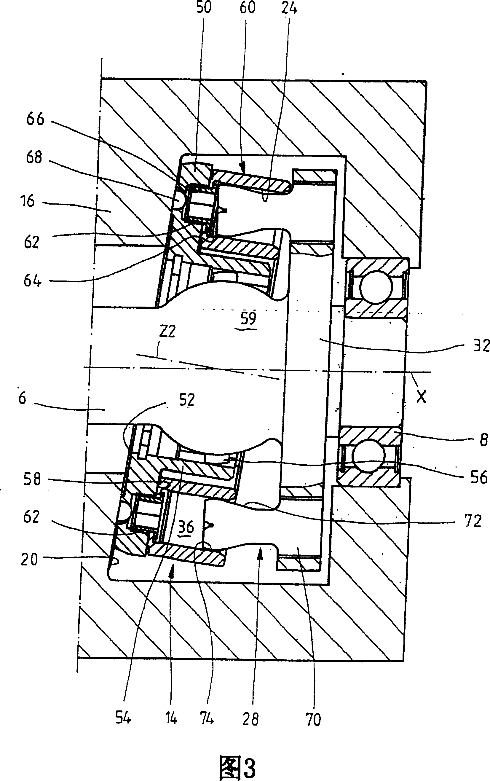
[0020] The two cylinder barrels 12 , 14 , which are inclined to one another, are supported on a control disk 16 accommodated in the housing 2 at the center (viewed according to FIG. 1 ). The end face of the control disk 16 is formed by two inclined surfaces 18 , 20 . According to FIG. 1 , these inclined surfaces 18 , 20 are mutually inclined in such a way that the control disk 16 tapers downwards fro...


PUM


Abstract

The invention relates to an axial piston machine comprising two cylinder drums which are guided in a housing, can be respectively rotated about a drum axis, and are respectively supported on an inclined surface arranged in the direction of a shaft rotational axis. According to the invention, said inclined surfaces are located in the region between the two cylinder drums and the channels for supplying and releasing pressure end in said two inclined surfaces, i.e. pressure is supplied and released centrally.

Description

technical field [0001] The invention relates to an axial piston machine according to the preamble of claim 1 . Background technique [0002] An axial piston machine of this type, known for example from WO 03 / 058034 A1, comprises two cylinder bores in each of which a plurality of cylinders are formed. Through the two cylinder bores are shafts fixedly connected to a plurality of pistons which define respective pressure chambers with the cylinders of the cylinder bores. The cylinder barrel is supported on an inclined surface, the inclination of which is chosen such that the axis of rotation of the cylinder barrel is inclined relative to the axis of the shaft. The inclined surface supporting the cylinder barrel does not rotate with the shaft or the cylinder barrel so that the piston follows an elliptical trajectory of motion relative to the plane in which the inclined surface supporting the cylinder barrel lies. In the known solution, the cylinder barrel is positioned such tha...

Claims


Application Information

Patent Timeline
Patent Type & Authority Applications(China)
IPC IPC(8): F04B1/24
CPCF04B1/24
Inventor 约尔格·丹托格雷伯鲁道夫·谢弗
Owner BOSCH REXROTH AG
Why Eureka
Try Eureka