
Master-salve switching method and system for mutual backup device

A switching system, master-slave technology, applied in the field of data communication, can solve problems such as inability to use flexibly and low work efficiency

Active Publication Date: 2007-03-14
NEW H3C TECH CO LTD
View PDF0 Cites 20 Cited by
  • Summary
  • Abstract
  • Description
  • Claims
  • Application Information

AI Technical Summary

Problems solved by technology

In this way, the work efficiency is often low due to the coordination problem between the devices, and the various functions provided by each device cannot be used flexibly.
At the same time, many devices are piled up in the computer room, causing a lot of burden on management and maintenance

Method used


Image

  • Master-salve switching method and system for mutual backup device
  • Master-salve switching method and system for mutual backup device
  • Master-salve switching method and system for mutual backup device

Examples


Embodiment Construction

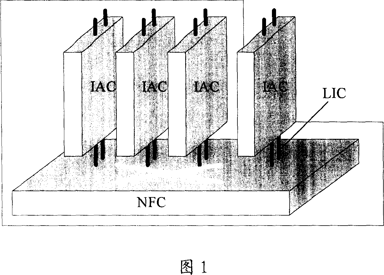
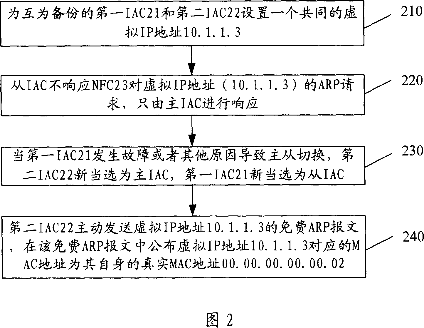
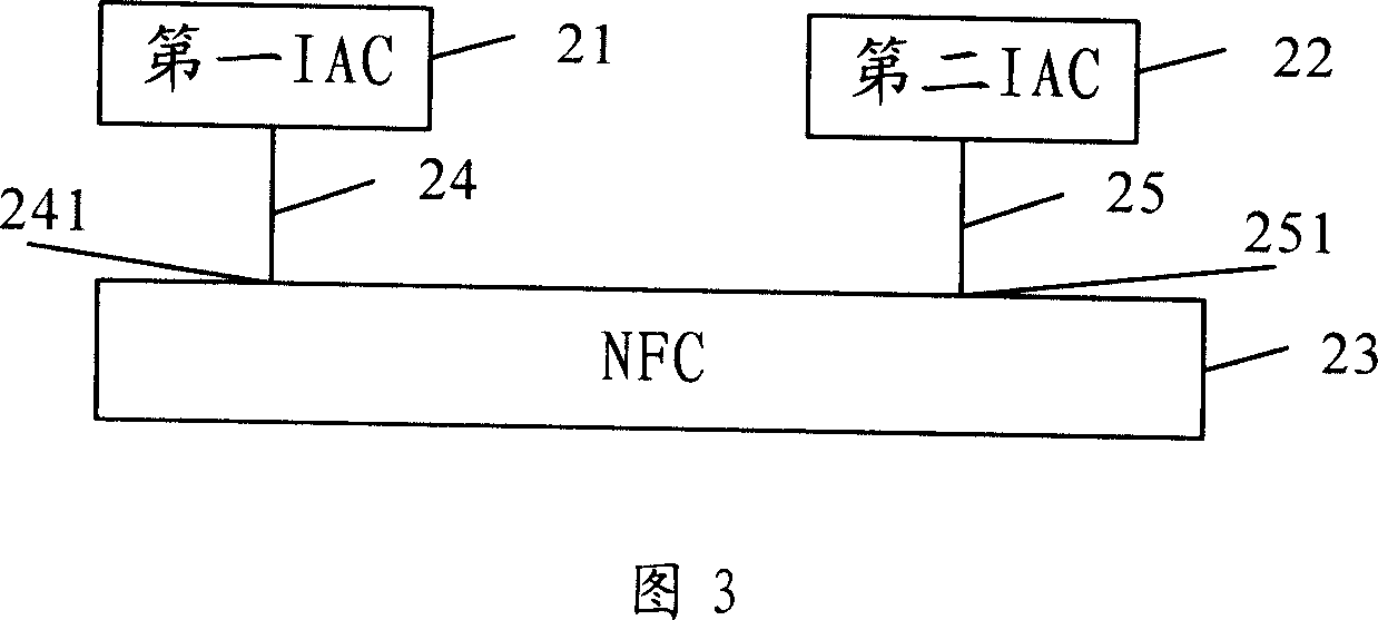
[0039] Please refer to FIG. 2 , which is a flow chart of the first embodiment of the master-slave switching method of the independent service components IAC that are mutually backup in an open application architecture OAA disclosed by the present invention. In order to make the description more specific, two IACs back up each other as an example for illustration. Please refer to FIG. 3 , which is a schematic diagram of a specific OAA architecture corresponding to a specific embodiment of the present invention. In the exemplary OAA architecture diagram shown in FIG. 3 , the first IAC21, the second IAC22, the NFC23, the ILC24 between the first IAC21 and the NFC23, and the ILC25 between the second IAC22 and the NFC23 are included.

[0040] The essence of ILC is the interface connector of IAC and NFC, through which devices from different manufacturers are connected together. ILC generally does not appear as an externally visible component, but is integrated on NFC and IAC as an in...


PUM


Abstract

This invention discloses one main switch method of backup device, which comprises the following steps: the device has same virtual IP address to deny ARP requirements to above virtual IP address; when selecting main device, addressing its self MAC address and virtual IP address relationship free ARP message to trigger NFC brushing ARP record. This invention discloses other backup device main switch method and one main switch system.

Description

technical field [0001] The invention relates to the field of data communication, in particular to a master-slave switching method that is a backup device for each other. Background technique [0002] In today's network world, the requirements for network equipment are not only the data forwarding capabilities provided by traditional routers and switches, but also require network equipment to support various applications. For example, it is required that the device can not only forward data, but also access voice; it can not only complete load sharing, but also perform content security filtering. Since it is difficult for any independent technology manufacturer to provide all the services required by customers at the same time, users need to purchase equipment from multiple manufacturers and perform networking and functional coordination of these equipment by themselves. This often leads to low work efficiency due to the coordination problem between devices, and the various ...

Claims


Application Information

Patent Timeline
IPC IPC(8): H04B1/74H04L1/22G06F11/00
Inventor 王飓
Owner NEW H3C TECH CO LTD
Learn More