Mobile phone baseband chip audio frequency switching device

A switching device and baseband chip technology, applied in branch office voice amplifiers and other directions, can solve the problems of occupying mobile phone board space and increasing the cost of peripheral devices, and achieve the effect of reducing system costs, optimizing mobile phone design, and reducing peripheral devices.

Active Publication Date: 2007-03-14
SPREADTRUM COMM (SHANGHAI) CO LTD
View PDF0 Cites 7 Cited by
  • Summary
  • Abstract
  • Description
  • Claims
  • Application Information

AI Technical Summary

Problems solved by technology

Doing so will increase the cost of peripheral co...

Method used


Image

  • Mobile phone baseband chip audio frequency switching device
  • Mobile phone baseband chip audio frequency switching device
  • Mobile phone baseband chip audio frequency switching device

Examples


Embodiment Construction

[0013] The present invention will be described in further detail below in conjunction with the accompanying drawings and specific embodiments.

[0014] As shown in Fig. 4 is the circuit diagram of a specific embodiment of the mobile phone audio switching device of the present invention, comprises a DSP, connects two-way DAC, and DSP provides signal to two-way DAC; The DAC is connected to the headphone output of the mobile phone through a switch.

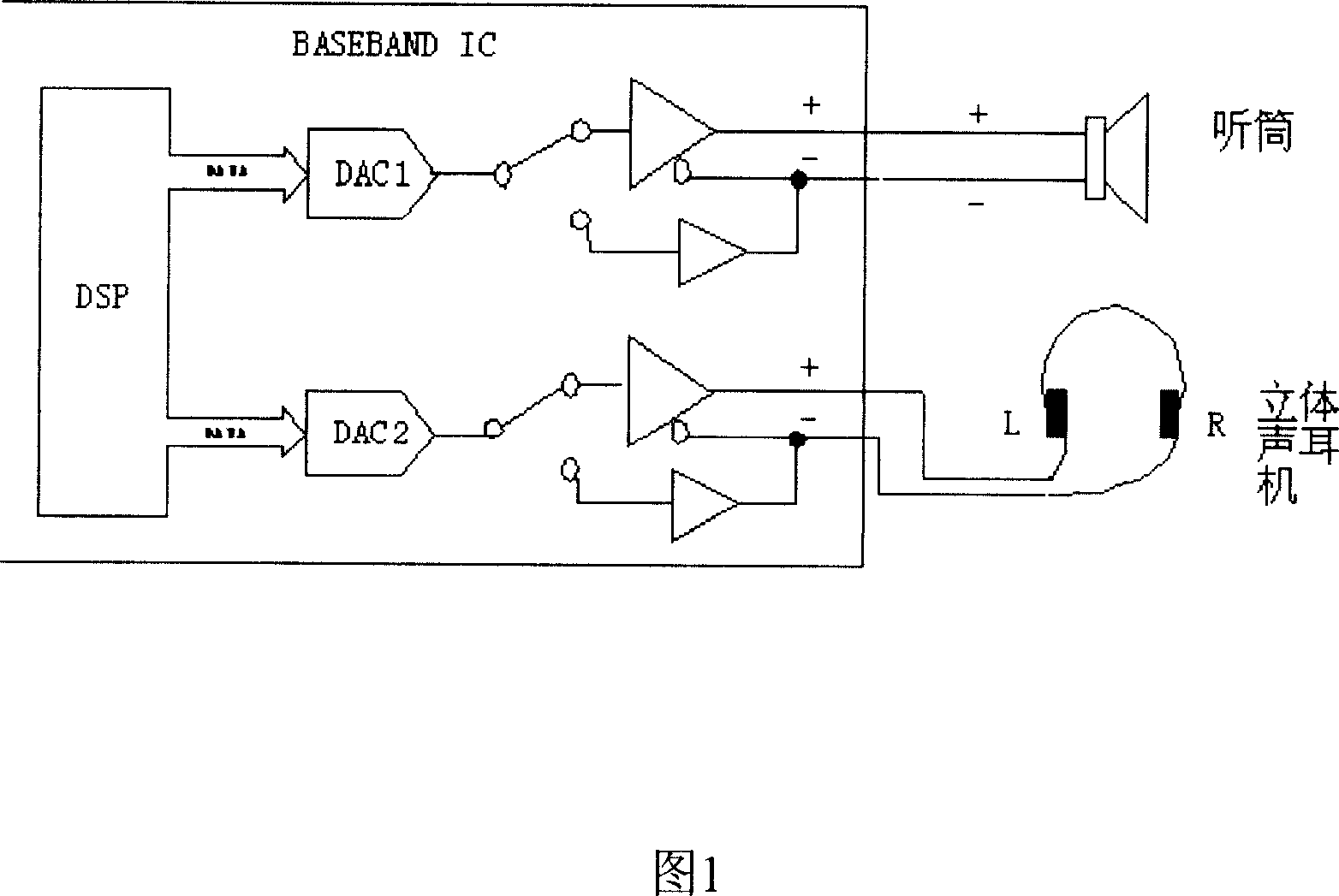
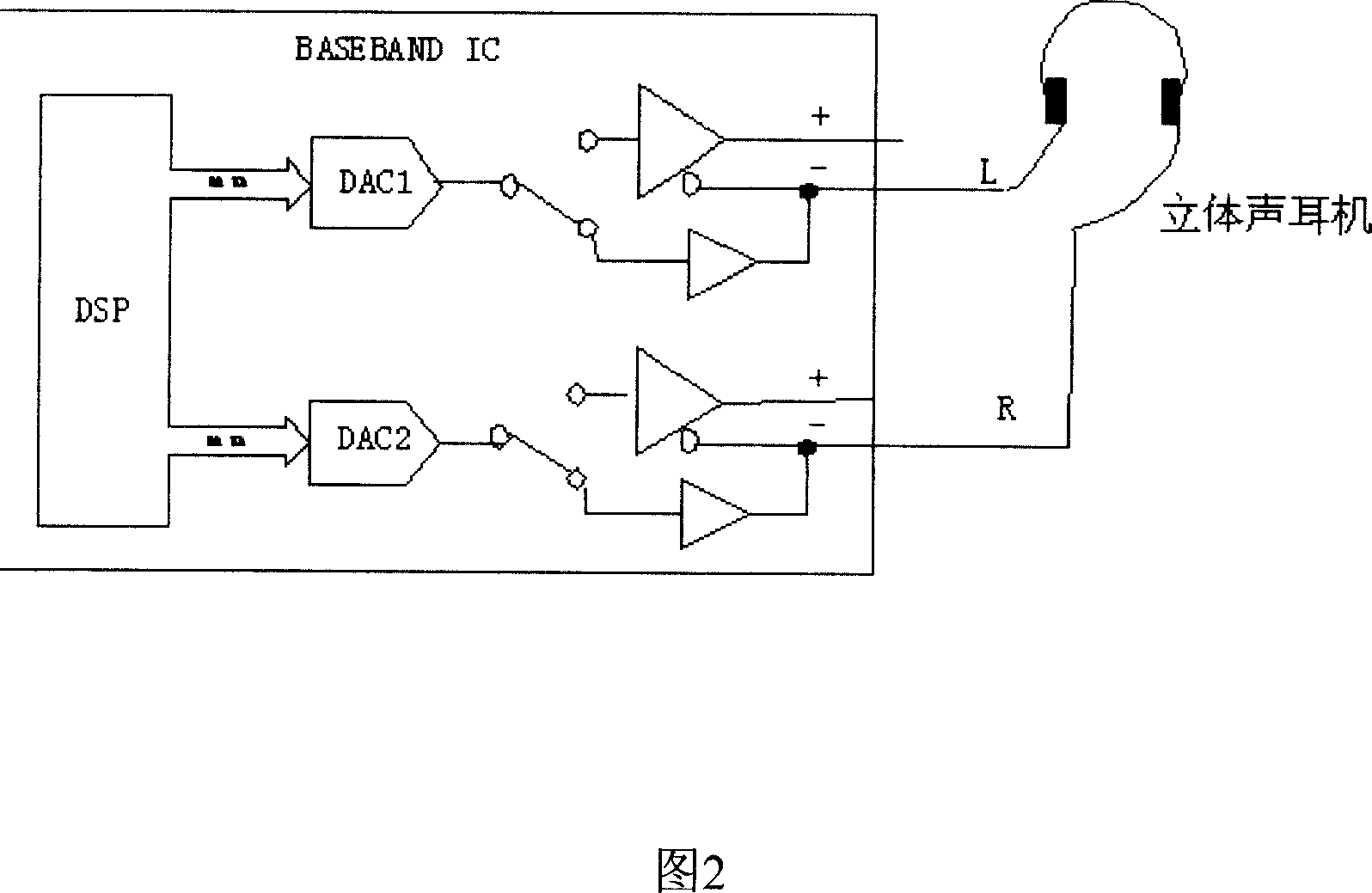
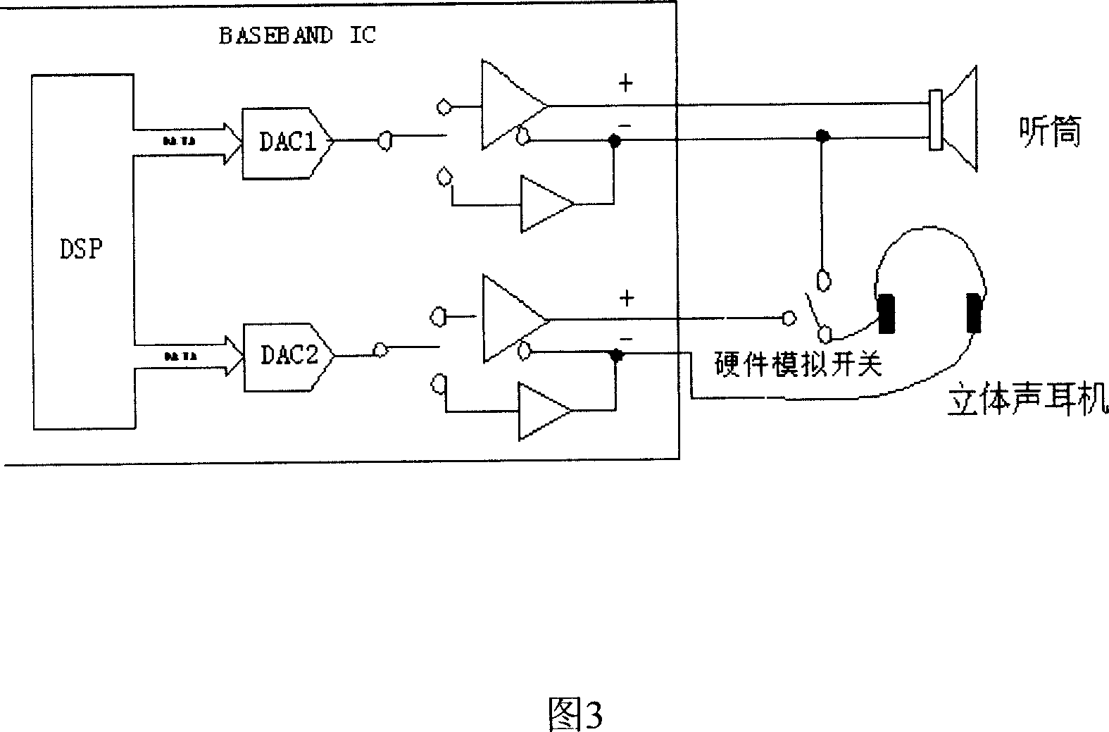
[0015] As shown in the figure, when corresponding to stereo signals such as MP3, the previous implementation method is continued. When using the headset for voice calls, the peripheral circuits remain unchanged. The internal DSP sends the same data to DAC-L and DAC-R, so that although the output from two different DACs is still the same voice analog signal, the voice function is realized.

[0016] The method for implementing the audio switching function is introduced in detail below in combination with the accompanying drawings:

...


PUM


Abstract

This invention discloses one cell phone chip audio frequency switch device, which comprises at least one DSP, connection circuit DAC, DSP to provide two paths of signals with one connected to cell phone output end and second end connected to the cell phone earphone. The DSP sends sound digital signals to one path of DAC with output analogue signals through operation difference to phone to realize call sound function and the DSP sends the left and right digital signals to the said one and second paths.

Description

technical field [0001] The invention relates to an audio switching device, in particular to a mobile phone baseband chip audio switching device. Background technique [0002] At present, the audio output of baseband chips common in mobile phones is usually two differential voice signals. As shown in Figure 1, differential signals are provided to the speaker on the mobile phone and the speaker on the earphone; the digital signal processor (DSP, Digital Signal Processor) inside the chip provides voice data to the digital / analog converter (DAC, Digital-to-Analog Converter) ), output differential analog signal. Figure 2 For stereo signals such as MP3, due to the different data of the left and right channels, the chip DSP needs to provide the left and right voice data to the two DACs respectively, and output two single-ended analog signals at the same time. Therefore, in general, from the perspective of the peripheral circuit, one of the two pairs of audio signals is taken as t...

Claims


Application Information

Patent Timeline
IPC IPC(8): H04M1/60
Inventor 朱伟
Owner SPREADTRUM COMM (SHANGHAI) CO LTD
Why Eureka
Try Eureka