Panel unloading and loading hig slicing filling mining method

A filling mining method and filling mining technology, applied in the direction of filling, ground mining, mining equipment, etc., can solve the inability to implement large-scale stope structure and large-scale mechanized mining operations, stope production capacity and mining efficiency constraints, stope Roof collapse and other problems, to achieve the effect of realizing large-scale mechanized mining operations, expanding the size of the stope structure, and improving the bearing capacity of the rock mass

Inactive Publication Date: 2007-03-21
CHINA MINMETALS CHANGSHA MINING RES INST
View PDF0 Cites 17 Cited by
  • Summary
  • Abstract
  • Description
  • Claims
  • Application Information

AI Technical Summary

Problems solved by technology

[0002] Under the condition of high in-situ stress, especially under the condition of high in-situ stress with the horizontal stress approximately parallel to the ore body trend as the maximum principal stress, metal ore mining is prone to the roof collapse of the stope and rockburst disasters. In order to prevent this phenomenon, The current technical means are to adopt smaller stope specifications and provide special reinforced support for the stope structure, so that it is impossible to implement large-scale stope structures and large-scale mechanized mining operations, and the production capacity and mining efficiency of the stope are seriously affected. Constraints, and increased mining costs (brought by enhanced support)

Method used


Image

  • Panel unloading and loading hig slicing filling mining method
  • Panel unloading and loading hig slicing filling mining method

Examples


Embodiment approach 1

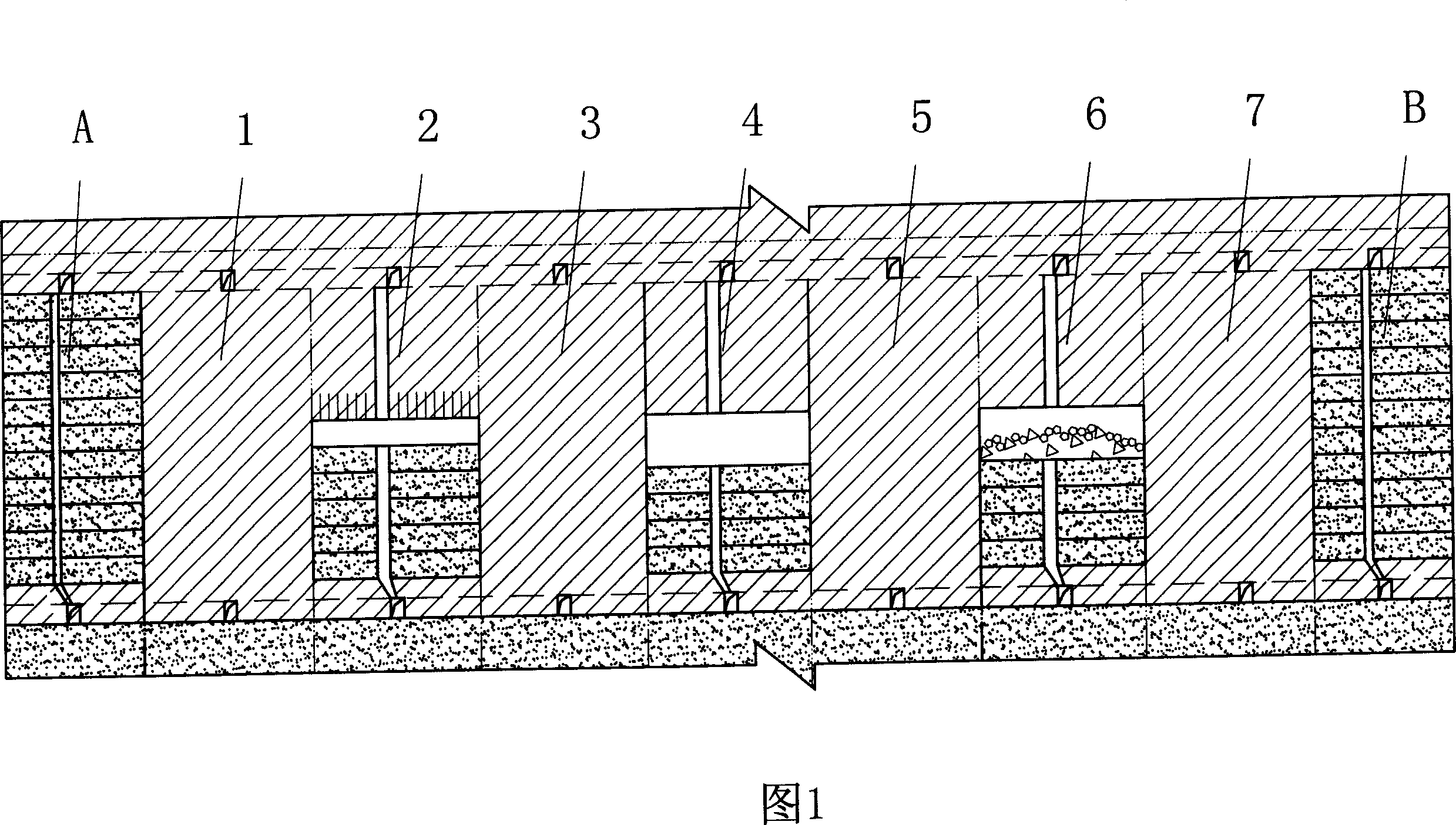
[0009] This is a high layer and fill mining method using only panel end unloading, which divides the ore body into mining panels along the strike direction of the ore body. It can be seen from Fig. 1 that in a mining panel, a vertical ore body trend vertical stope (A, B) is arranged at both ends, and multiple vertical ore body trends are arranged between the vertical stopes A and B Panel stopes (1-7). Vertical slot stopes (A, B) and panel stopes (1-7) are mined by upward layered filling mining method, and tailing sand cemented filling is carried out after mining. However, the vertical slot stope (A, B) must be recovered and filled ahead of the panel stope (1-7). The stope is mined and filled, and the layer height of the vertical groove stope is preferably lower than that of the panel stope, and the width of the vertical groove stope is narrower than the width of the panel stope. In this embodiment, the layer height of the stope of the vertical slot is 2-3m, and the width is ...

Embodiment approach 2

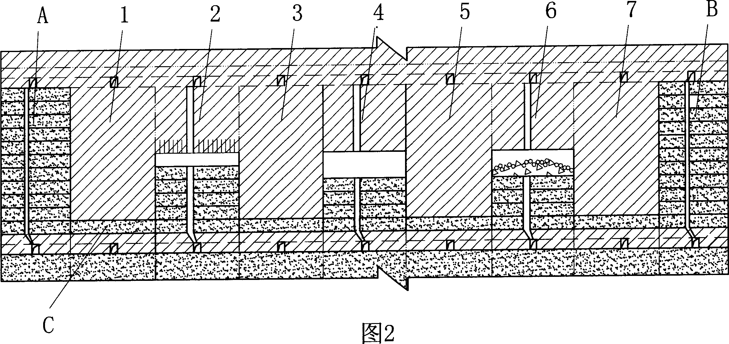
[0011] This is a high-layer filling mining method of unloading at the bottom and end of the panel. The ore body is divided into mining panels along the strike direction, and the bottom stope C is arranged at the bottom of the mining panel, and the two ends of the panel are respectively arranged. Vertical channel stopes (A, B) vertical to the ore body, and a plurality of panel stopes (1-7) vertical to the vertical ore body are arranged between the vertical channel stopes. It can be seen from Figure 2 that this arrangement is different from Embodiment 1, and it can be seen that in this embodiment, the bottom stope C at the bottom of the mining panel is firstly mined by the comprehensive method, and the tailings are cemented after mining filling. The mining and filling operations of vertical slot stopes (A, B) and panel stopes (1-7) are the same as those in Embodiment 1, and will not be described again. In this embodiment, the bottom stope and the vertical groove stope are mined...


PUM


Abstract

The present invention discloses a panel unloading high-slicing filling mining method. Said method includes the following steps: dividing the ore body into mining panel along the strike direction of ore body; in two ends of said panel respectively arranging buttock stope perpendicular to the strike of ore body; between two buttock stopes arranging several panel stopes perpendicular to the strike of ore body; and in the buttock stope and panel stope adopting upwards high-slicing filling mining method to make backstopping operation.

Description

technical field [0001] The invention relates to a panel unloading high-layer filling mining method. Background technique [0002] Under the condition of high in-situ stress, especially under the condition of high in-situ stress with the horizontal stress approximately parallel to the ore body trend as the maximum principal stress, metal ore mining is prone to the roof collapse of the stope and rockburst disasters. In order to prevent this phenomenon, The current technical means are to adopt smaller stope specifications and provide special reinforced support for the stope structure, so that it is impossible to implement large-scale stope structures and large-scale mechanized mining operations, and the production capacity and mining efficiency of the stope are seriously affected. Constraints, and increased mining costs (brought by enhanced support). Therefore, how to solve the difficulties brought by high geostress to the mining of metal deposits is a technical problem to be ...

Claims


Application Information

Patent Timeline
Patent Type & Authority Applications(China)
IPC IPC(8): E21C41/22E21F15/00
Inventor 周爱民李向东
Owner CHINA MINMETALS CHANGSHA MINING RES INST
Why Eureka
Try Eureka