CM rate assigning method and system

A rate, preset technology, applied in the field of network communication

Active Publication Date: 2007-03-21
HUAWEI TECH CO LTD
View PDF0 Cites 3 Cited by
  • Summary
  • Abstract
  • Description
  • Claims
  • Application Information

AI Technical Summary

Problems solved by technology

[0018] The purpose of the present invention is to provide a CM rate designation method and system that will not cause link disconnection when the CM rate is designated

Method used


Image

  • CM rate assigning method and system
  • CM rate assigning method and system
  • CM rate assigning method and system

Examples


Embodiment Construction

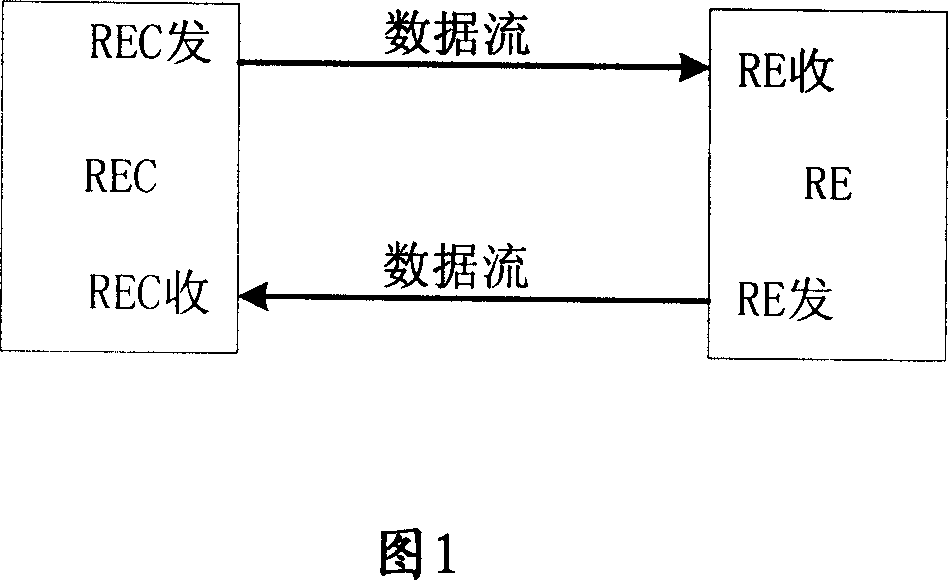
[0058] The core of the present invention is that the wireless device control end specifies the CM rate supported by the wireless device end for itself by performing local CM rate negotiation and interacting with the rate information of the wireless device; The CM rate of the control terminal is the same as the CM rate, so that the wireless device control terminal and the wireless device end can work at the same CM rate.

[0059] Specifically, the present invention first needs to enter the normal working state of the system, and then specify the CM rate.

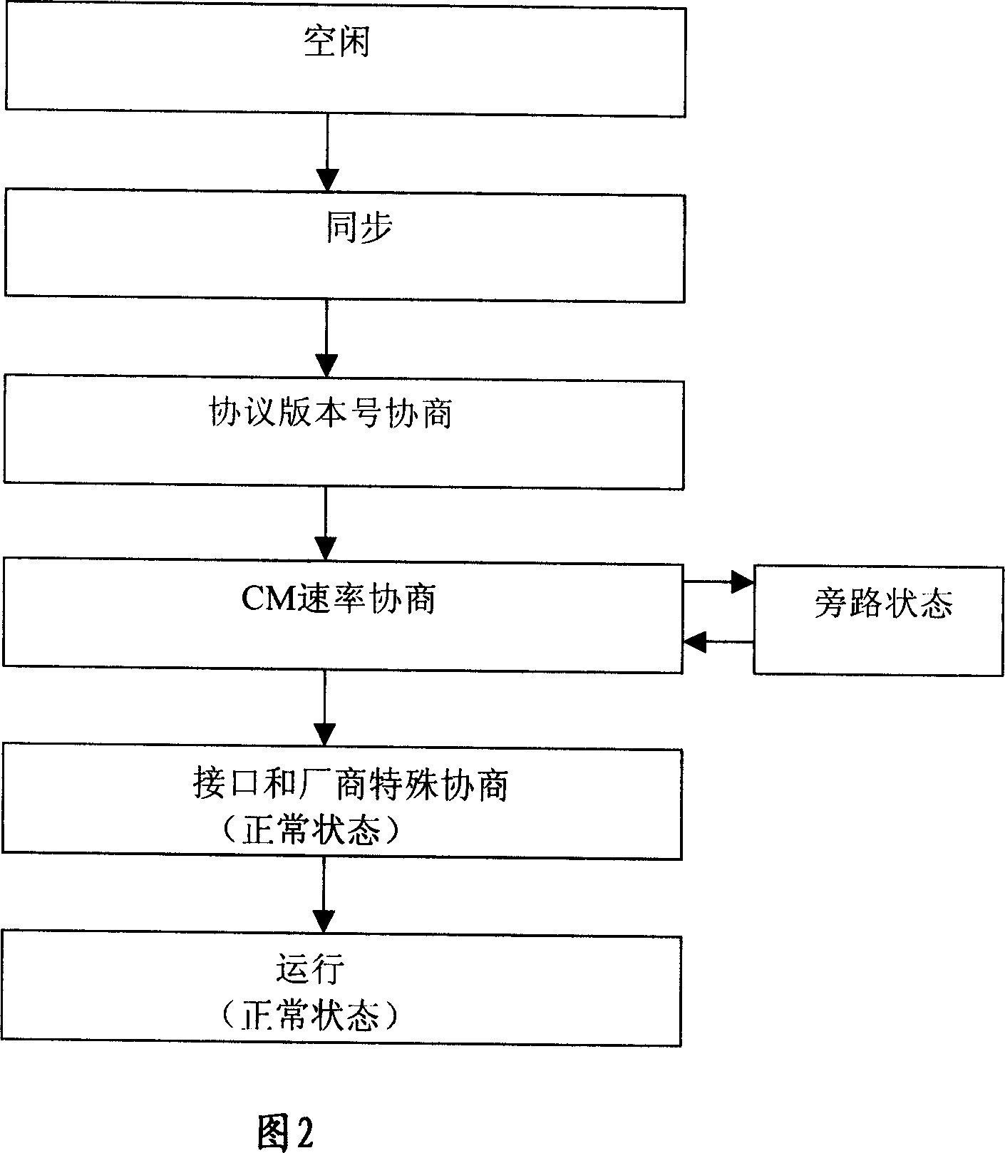
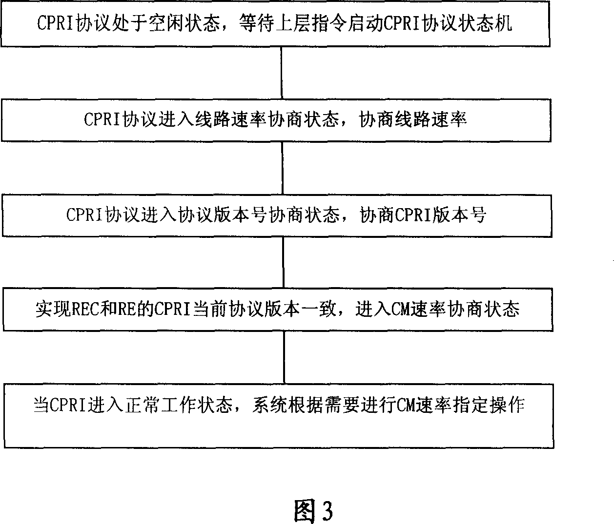
[0060] The process before the system enters the normal working state is from the time when the system is powered on and starts to work until the system enters the normal working state, which includes:

[0061] When the system is powered on and starts to work, the CPRI protocol is in the idle state at this time, and the protocol in the idle state waits for the upper layer protocol to issue an instruction to start the CPRI prot...


PUM


Abstract

A method for assigning CM rate includes entering consultation state after CM rate information is interacted with radio device end by radio device control end, setting assigned CM rate on radio device control end by up-layer software of radio device control end, sending its CM rate to radio device end by said control end then entering radio device end to consultation state, setting CM rate on said control end to be CM rate of radio device end by up-layer software of radio device end when radio device end being entered into consultation state is found by up-layer software of radio device end.

Description

technical field [0001] The present invention relates to the technical field of network communication, in particular to a CM rate designation method and system. Background technique [0002] CPRI (Common Protocol Radio Interface) is a general wireless interface protocol used in wireless communication systems, responsible for defining the key internal interface of the wireless base station between the wireless equipment control end (REC) and the wireless equipment end (RE). The goal of the standard is to create an open market for cellular base stations, thereby substantially reducing the large development effort and expensive costs that have long accompanied base station design. [0003] The establishment of CPRI is conducive to the standardization of wireless base station supporting products, enabling communication equipment manufacturers to selectively purchase wireless base station subsystems, thereby increasing the speed of product development, shortening the time to marke...

Claims


Application Information

Patent Timeline
Patent Type & Authority Applications(China)
IPC IPC(8): H04L29/06H04L12/56H04W28/22
Inventor 蒋培刚
Owner HUAWEI TECH CO LTD
Why Eureka
Try Eureka