Supercharge Your Innovation With Domain-Expert AI Agents!

Back suspension device

A technology of rear suspension and suspension, applied in the direction of suspension, elastic suspension, transportation and packaging, etc., can solve the problems of low rigidity and deterioration of component setting performance.

Active Publication Date: 2010-05-26
MAZDA MOTOR CORP
View PDF7 Cites 0 Cited by
  • Summary
  • Abstract
  • Description
  • Claims
  • Application Information

AI Technical Summary

Problems solved by technology

[0004] However, in the above-mentioned conventional rear suspension device, the swing arm (suspension trailing arm) is a press-formed part integrally formed with the rear wheel support member (wheel support device), so the rigidity is generally low. The other end of the lateral link (lateral link) that extends in the width direction of the vehicle body and is installed on the vehicle body freely at one end requires additional reinforcement brackets or reinforcement of the mounting portion, which deteriorates the performance of component installation

Method used


Image

  • Back suspension device
  • Back suspension device
  • Back suspension device

Examples


Embodiment Construction

[0030] Hereinafter, embodiments of the present invention will be described with reference to the drawings.

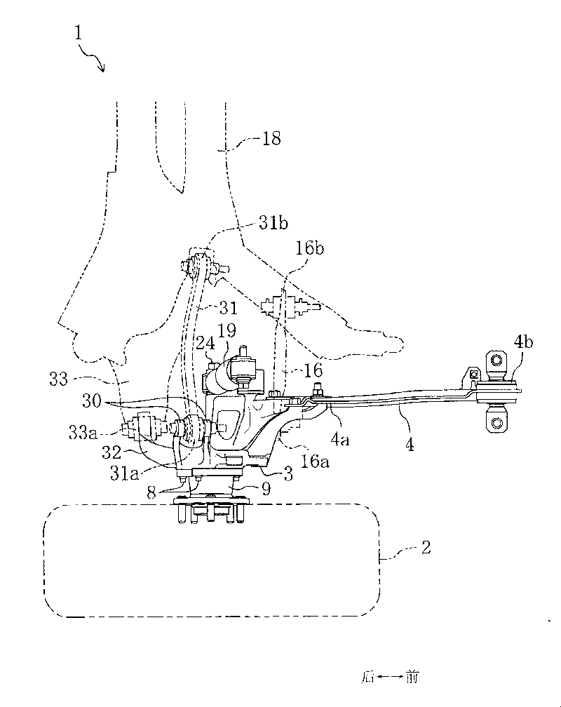
[0031] figure 1 and figure 2 The rear suspension device 1 according to the embodiment of the present invention is shown in . The rear suspension device 1 includes a wheel support device 3 that rotatably supports a wheel 2 (rear wheel), and extends in the front-rear direction of the vehicle. The rear end 4a is mounted on the wheel support device 3, and the front end 4b is mounted on the Suspension trailing arm 4 on the vehicle body such as rear vehicle frame (not shown).

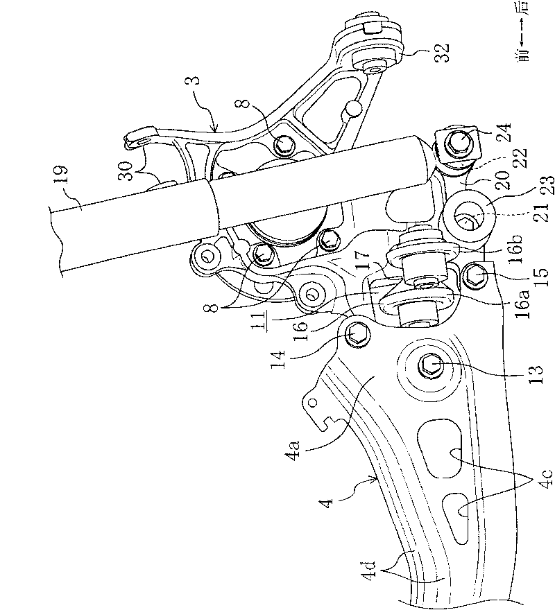
[0032] Such as Figure 3 to Figure 5 As shown, the above-mentioned suspension trailing arm 4 is a stamped part formed by stamping a steel plate, and is provided with an opening 4c, a corner line 4d, etc. to moderately bend, thereby allowing the camber angle of the wheel 2 to change. The rear end 4a of the suspension trailing arm 4 is formed with three screw penetration holes (not shown) that are s...


PUM


Abstract

The present invention provides a rear suspension device comprising a wheel support equipment for freely rotatablely supporting a wheel, a suspension trailing arm which extends in the front and rear directions of a vehicle and has a rear end mounted to said wheel support equipment and a front end freely rotatablely mounted to a vehicle body so as to be swingable formed to allow an outer-obliquity angle change of the wheel, a lateral link which one end is freely rotatablely mounted to said wheel support equipment and the other end is freely rotatablely mounted to a vehicle body, a plurality of fastening parts for fastening the trailing arm to the wheel support, a lateral link mounting part formed on a wall surface which forms an opening of a place surrounded by the plurality of the fasteningparts of the wheel support. Thus, it is possible to surely support a lateral link while securing an excellent package placement property without forming a bracket for mounting an additional link in arear suspension device.

Description

technical field [0001] The invention relates to a rear suspension device of a vehicle. Background technique [0002] The known vehicle rear suspension device in the past includes a suspension extending along the front and rear direction of the vehicle, one end is mounted on the wheel support device, and the other end is mounted on the vehicle body freely, and the camber angle (camber angle) of the wheel is allowed to change. trailing arm. [0003] Such a rear suspension device, as shown in Japanese Patent Laid-Open Publication No. 2003-112508, includes a swing arm (suspension trailing arm) made of a stamped and formed steel plate. The front end part of the vehicle body is used to connect the rear wheel support member to the rear part of the vehicle body, and the shock absorber support member is attached to the lower part of the vehicle body. The rear suspension allows the camber angle of the wheel to vary by moderately bending the stamped swing arm. [0004] However, in t...

Claims


Application Information

Patent Timeline
Patent Type & Authority Patents(China)
IPC IPC(8): B60G3/20
Inventor 佐野晋田中洋岩野光男
Owner MAZDA MOTOR CORP
Features
  • R&D
  • Intellectual Property
  • Life Sciences
  • Materials
  • Tech Scout
  • Unparalleled Data Quality
  • Higher Quality Content
  • 60% Fewer Hallucinations
Learn More