Lift axle suspension system

a technology of lift axle and suspension system, which is applied in the direction of resilient suspension, interconnection system, vehicle spring, etc., can solve the problems of difficult to achieve the goals of increasing compactness, reducing weight, and particularly difficult to achieve in the direction of steerable suspension system

Inactive Publication Date: 2005-03-29
WATSON & CHALIN MFG INC
View PDF35 Cites 24 Cited by
  • Summary
  • Abstract
  • Description
  • Claims
  • Application Information

AI Technical Summary

Problems solved by technology

However, these objectives are particularly difficult to achieve in steerable suspension systems, due to the fact that so many functions are performed by these suspension systems....

Method used


Image

  • Lift axle suspension system
  • Lift axle suspension system
  • Lift axle suspension system

Examples


Embodiment Construction

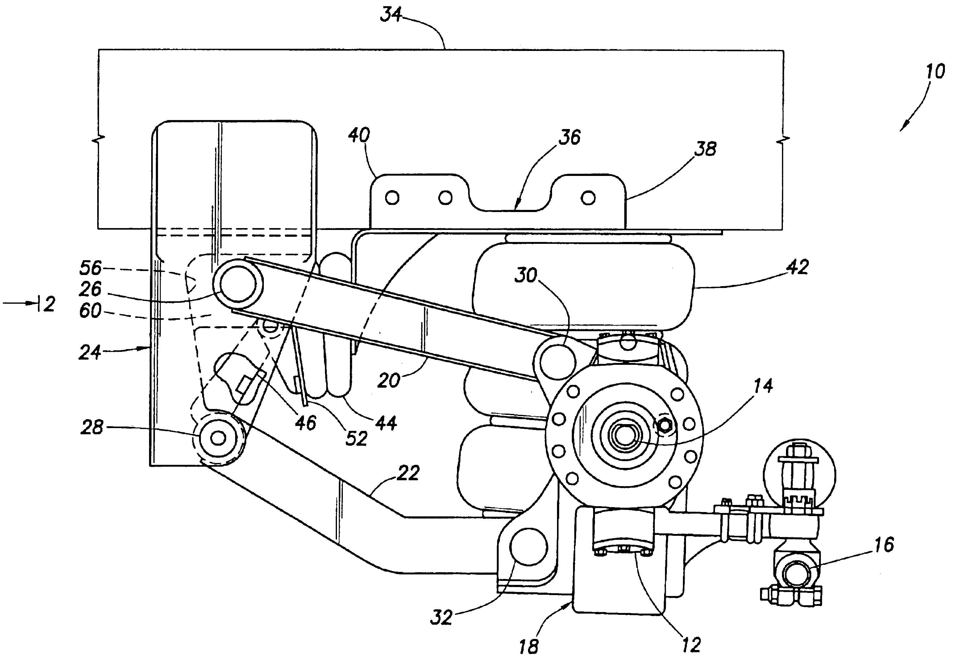
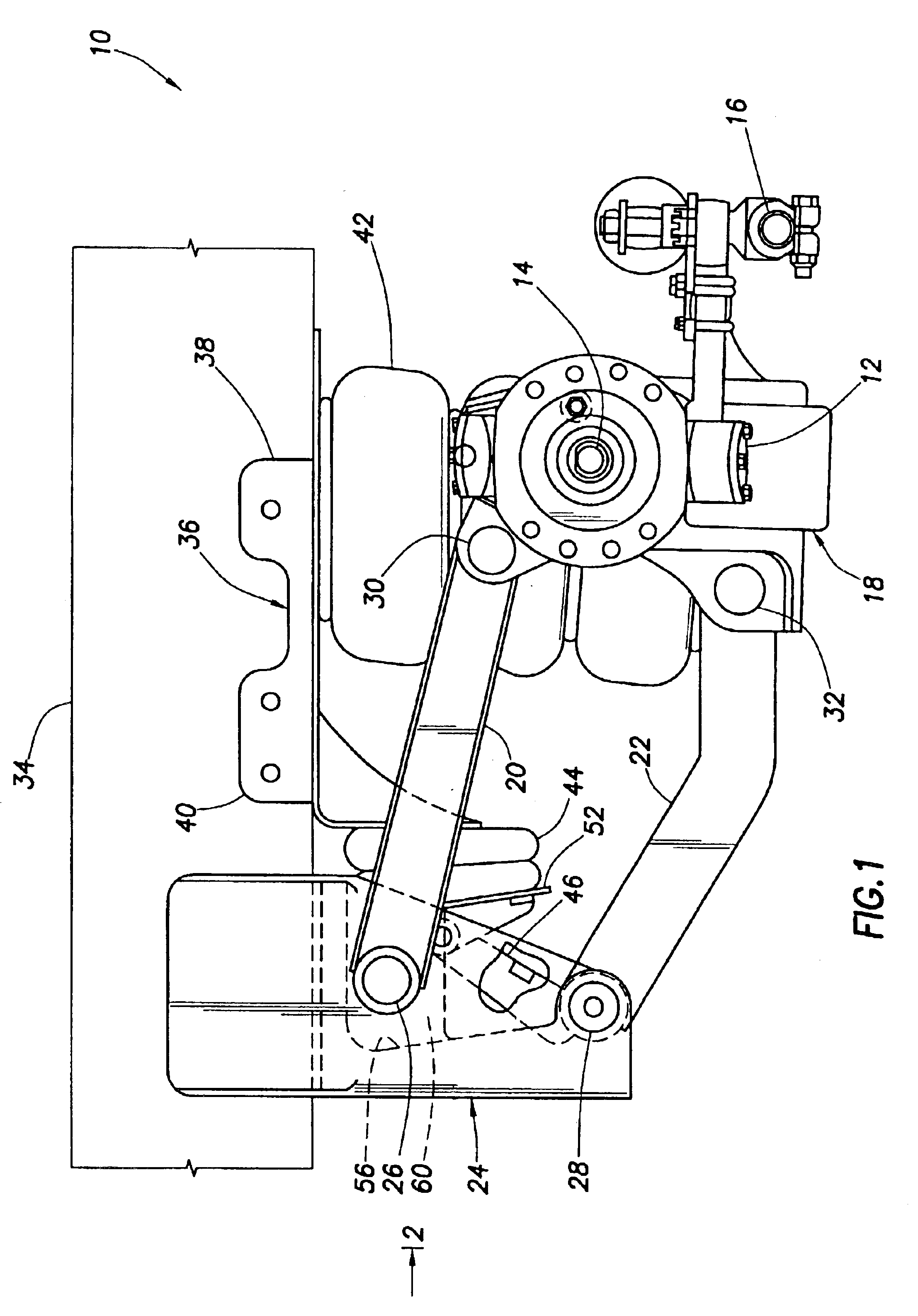
Representatively illustrated in FIG. 1 is a steerable lift axle suspension system 10 which embodies principles of the present invention. In the following description of the suspension system 10 and other apparatus and methods described herein, directional terms, such as “above”, “below”, “upper”, “lower”, etc., are used only for convenience in referring to the accompanying drawings. Additionally, it is to be understood that the various embodiments of the present invention described herein may be utilized in various orientations, such as inclined, inverted, horizontal, vertical, etc., and in various configurations, without departing from the principles of the present invention.

The suspension system 10 is described herein as being a steerable suspension system. For this purpose, a king pin housing 12 for pivotably mounting a spindle 14, a tie rod 16, etc., are connected at each opposite end of an axle assembly 18 of the suspension system 10. However, it should be clearly understood th...


PUM


Abstract

A lift axle suspension system. In a described embodiment, a lift axle suspension system includes: an axle assembly; an air spring connected between the axle assembly and a bracket attached to a vehicle frame; a trailing arm attached to the axle assembly; and a lift air spring. The lift air spring is connected between the bracket and the trailing arm, so that the axle assembly is lifted when the lift air spring is extended.

Description

BACKGROUNDThe present invention relates generally to suspension systems for wheeled vehicles and, in an embodiment described herein, more particularly provides a steerable lift axle suspension system.Those skilled in the art of vehicle suspension system design and manufacture know that it is becoming increasingly important to provide suspension systems which have reduced weight, and which are more compact. These objectives are sought for all types of suspension systems, including steerable lift axle suspension systems. However, these objectives are particularly difficult to achieve in steerable suspension systems, due to the fact that so many functions are performed by these suspension systems.For example, a typical liftable steerable suspension system must perform the functions of lifting an axle assembly relative to a vehicle frame, allowing the tires to steer, carrying loads and providing an acceptable ride quality. These last functions are many times satisfied by using a paralle...

Claims


Application Information

Patent Timeline
IPC IPC(8): B60G7/02B60G9/00B62D61/12B62D61/00
CPCB60G7/02B60G9/00B62D61/12B60G2200/314B60G2202/152B60G2204/4302B60G2204/47B60G2206/601B60G2204/143
Inventor CHALIN, THOMAS N.
Owner WATSON & CHALIN MFG INC
Why Eureka
Try Eureka