Pivot bearing

a bearing and pivoting technology, applied in the direction of pivoted suspension arms, suspensions that are resilient, interconnection systems, etc., can solve the problems of limiting the effectiveness of the bush, too stiff for satisfactory load absorption, and the performance of the bush is clearly limited

Inactive Publication Date: 2007-08-07
MERITOR HEAVY VEHICLE SYST
View PDF4 Cites 24 Cited by
  • Summary
  • Abstract
  • Description
  • Claims
  • Application Information

AI Technical Summary

Problems solved by technology

This limits the effectiveness of the bush because the stiffness / resilience requirements at different angularly positioned parts of the bush around the pivot may vary appreciably in practice according to the direction in which loads are exerted on the bush in use.
If the bush is heavily loaded in use, it will usually have a high level of stiffness which makes it too stiff for satisfactory absorption of loads.
Alternatively, if the bush is made with a compromised level of stiffness / resilience for the range of loads exerted on it in use in different directions, its performance is clearly limited.
However, the stiffness provided in the generally longitudinal direction is limited and may be insufficient to cope satisfactorily with increasing loading conditions under which some vehicles are expected to operate.

Method used


Image

  • Pivot bearing
  • Pivot bearing
  • Pivot bearing

Examples


Embodiment Construction

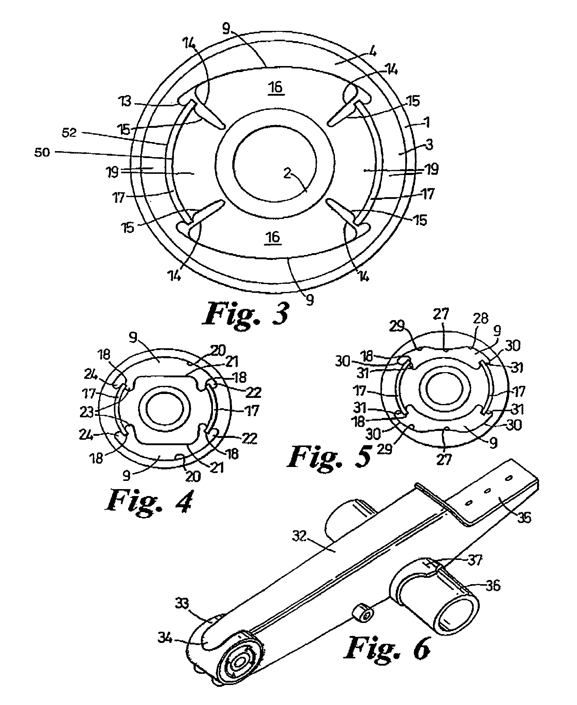
[0029]The pivot bearing in this embodiment of the present invention is to be used in a vehicle trailing arm suspension system.

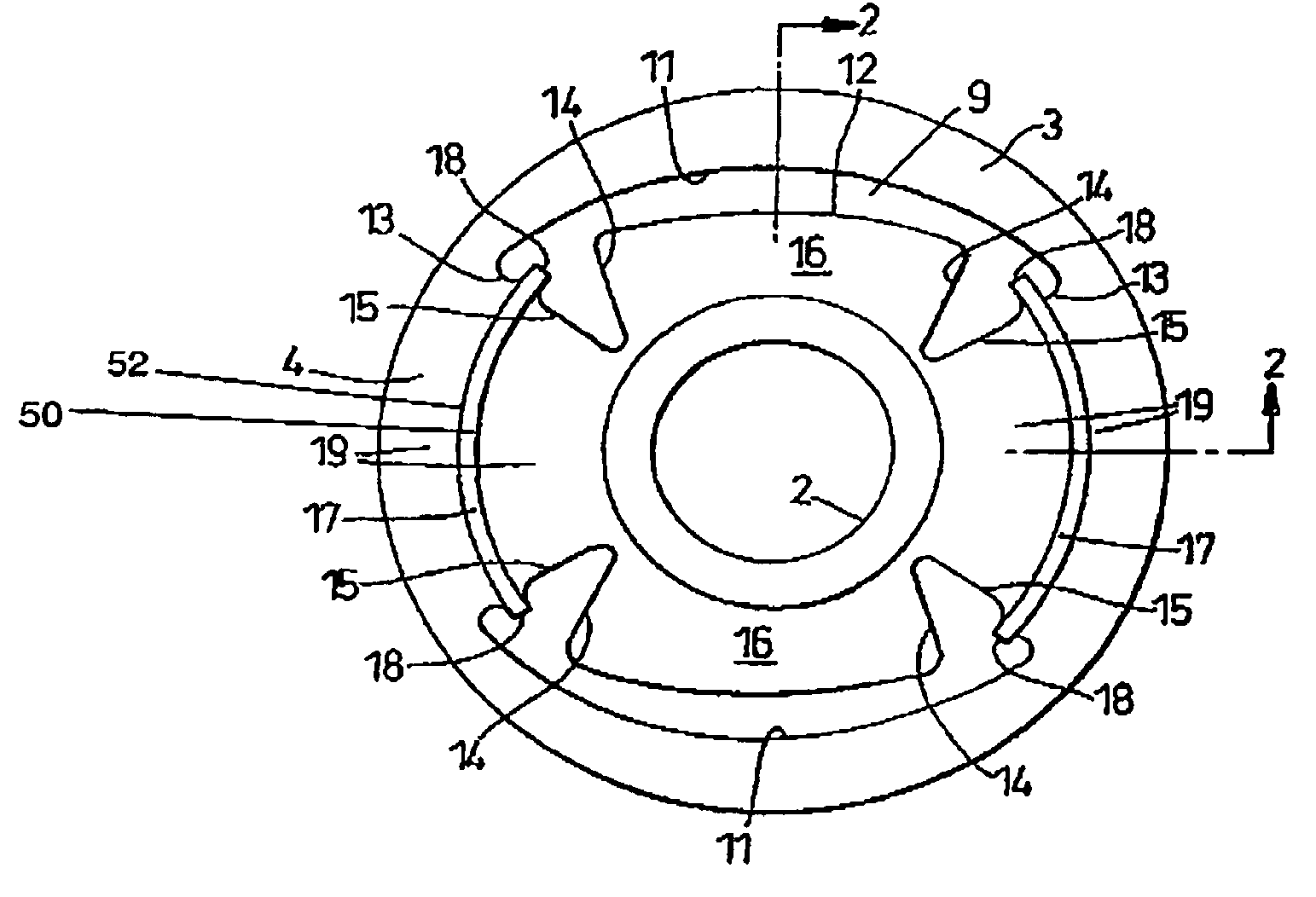
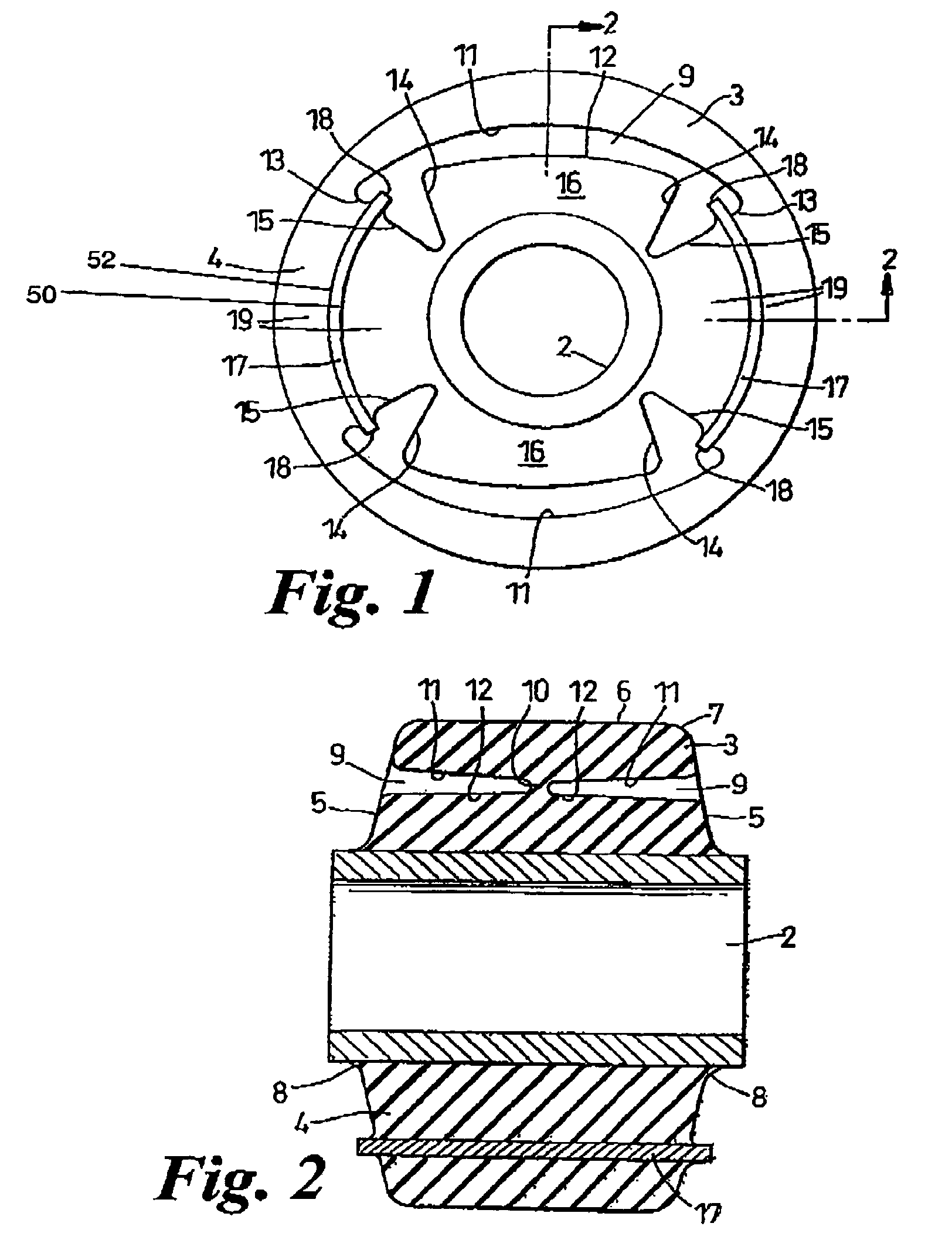
[0030]Referring to FIG. 3, the pivot bearing comprises a housing 1, an axial sleeve 2 and a bush 3.

[0031]The housing 1 is cylindrical and made of circular section steel tube. The sleeve 2 is also made of a circular section steel tube and is longer than the housing 1.

[0032]The bush 3, as best seen in FIGS. 1, 2 and 3, includes a cylindrical body 4 of a rubber material having a substantial degree of stiffness, but some resilience. The body 4 is concentrically molded onto, and bonded to, the sleeve 2. The body 4 has an external diameter such that it has to be radially compressed to fit into the housing 1 and a length that is fully received at its outer cylindrical surface into the housing 1. Opposite end faces 5 are shallowly frusto-conical. The end faces 5 merge into the external cylindrical surface 6 of the body 4 at convexly radiused edges 7 and meet the exte...


PUM


Abstract

A pivot bearing used in a vehicle trailing arm suspension includes a housing, a resilient bush compressed and bonded in the housing, and a rigid axial sleeve in the bush. The bush has voids, above and below the sleeve when the pivot bearing is fitted for use and stiffening elements which extend between the voids at opposite sides of the sleeve. When the pivot bearing is in use in a vehicle trailing arm suspension, the voids increase flexibility of the bush under generally vertical loading on the pivot bearing. The stiffening elements enhance the stiffness of the bush in generally horizontal direction for improved vehicle dynamics and reduced vibration. Preferably, the stiffening elements are of plate or leaf form, are bonded to the bush, and extend arcuately about the sleeve. The voids extend partially through the axial thickness of the bush from opposite ends of the bush and generally accurately about the sleeve. The bush also has enlarged opposite circumferential end portions. The end portions extend circumferentially beyond diametrically opposite parts of the external circumference of the sleeve and are in-turned towards the sleeve. Edges of the stiffening elements extend into the opposite end portions of the voids.

Description

[0001]This application is the National Stage of International Application PCT / GB01 / 03908 filed Aug. 31, 2001.BACKGROUND OF THE INVENTION[0002]This invention relates to a pivot bearing, particularly, though not exclusively, for a vehicle trailing arm suspension.[0003]Pivot bearings in a vehicle trailing arm suspension are subjected, in use, to forces in the vertical, horizontal, axial and torsional directions. It is desirable that the bearings be able to absorb these forces, including shock and out of phase wheel loading, and have a prolonged useful life.[0004]Conventionally, pivot bearings for vehicle trailing arm suspension systems include a housing containing a generally cylindrical bush on a rigid axial sleeve in which a pivot of a trailing arm is located. Whilst being essentially stiff, the bush has some resilience intended to absorb vertical, horizontal and torsional forces, particularly roll induced forces and out of phase wheel loads. Usually, the bush is made of a rubber mat...

Claims


Application Information

Patent Timeline
Patent Type & Authority Patents(United States)
IPC IPC(8): B60G3/12B60G7/02B60G9/00F16F1/371F16F1/387
CPCB60G7/02B60G9/003F16F1/371F16F1/387B60G2200/31B60G2204/143B60G2204/4104
Inventor HUGHES, THOMAS
Owner MERITOR HEAVY VEHICLE SYST
Why Eureka
Try Eureka