
Vehicle suspension system and height control valve therefor

Inactive Publication Date: 2006-04-18
HALDEX BRAKE
View PDF32 Cites 24 Cited by
  • Summary
  • Abstract
  • Description
  • Claims
  • Application Information

AI Technical Summary

Benefits of technology

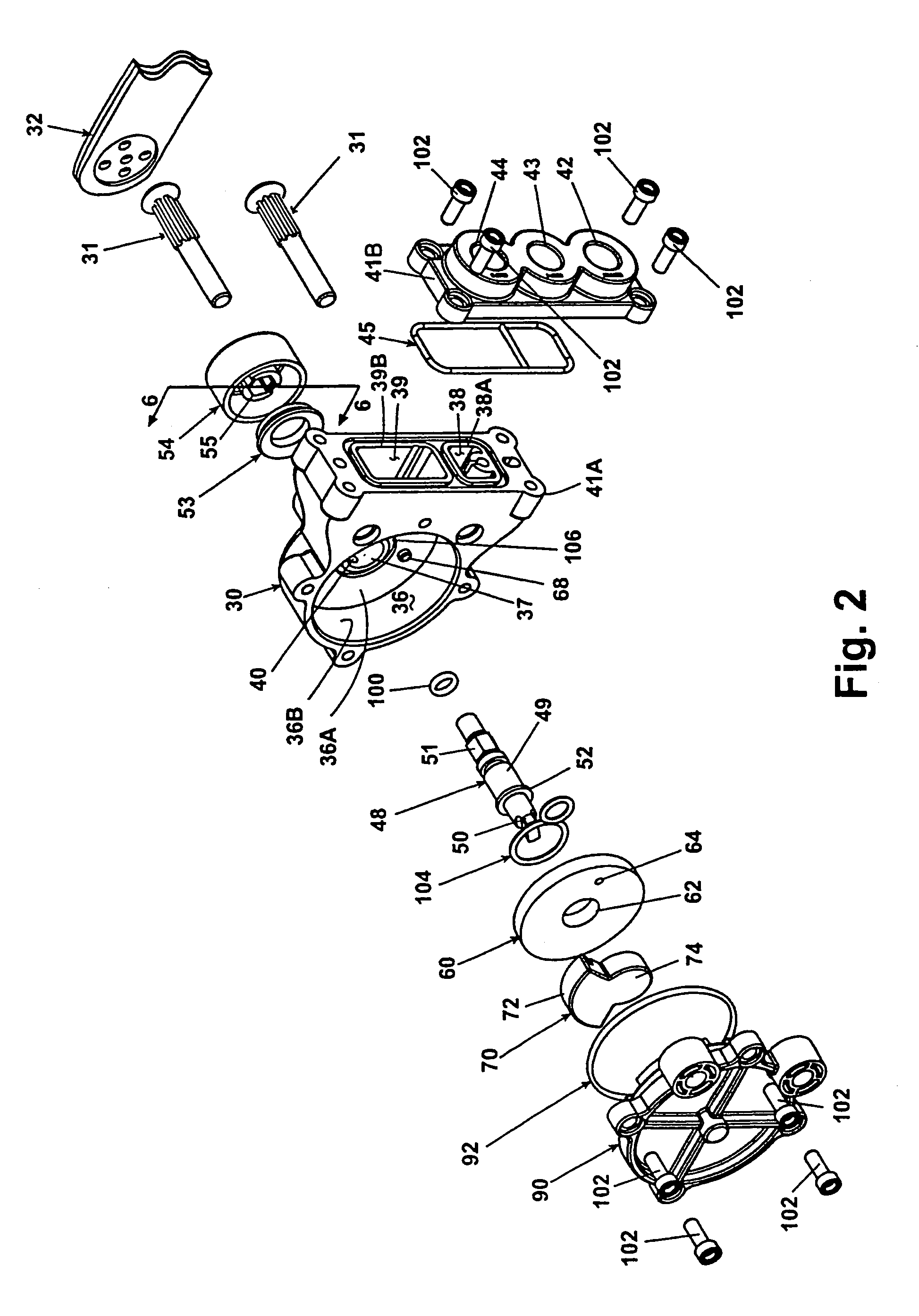
[0012]The invention relates to a height control valve for controlling the relative height between a vehicle frame and a trailing arm suspension. The trailing arm suspension comprises a trailing arm having one end pivotally mounted to the vehicle frame and carrying an axle that rotatably mounts ground engaging wheels. An air spring is positioned between another end of the trailing arm and the vehicle to resist the rotation of the trailing arm relative to the frame. The height control valve according to the invention preferably comprises a housing defining an interior chamber and having an inlet port fluidly connected to a source of pressurized air. An outlet port is provided in the housing for fluidly connecting to the air spring. Additionally, an exhaust port is provided in the housing for fluidly connecting to the atmosphere. A valve is disposed within the interior chamber and is selectively operable between a fill position, an exhaust position, and a neutral position. In the fill position, the air spring port is fluidly connected to the inlet port to introduce pressurized air from the air source into the spring. In the exhaust position, the air spring port is fluidly connected to the exhaust port to permit the exhaustion of pressurized air from the air spring. In the neutral position, the air spring port is not fluidly connected to either the inlet port or the exhaust port. By moving the valve between the neutral, fill and exhaust positions, it is possible to expand or deflate the air spring and thereby adjust the relative height of the vehicle frame to the trailing arm.

Problems solved by technology

Any movement of the wheels in response to their contact with the ground will result in a rotation of the trailing arms, which is dampened by the air springs.
These “dynamic” seals are subject to wear as the piston reciprocates, leading to their eventual failure.

Method used


Image

  • Vehicle suspension system and height control valve therefor
  • Vehicle suspension system and height control valve therefor
  • Vehicle suspension system and height control valve therefor

Examples


Embodiment Construction

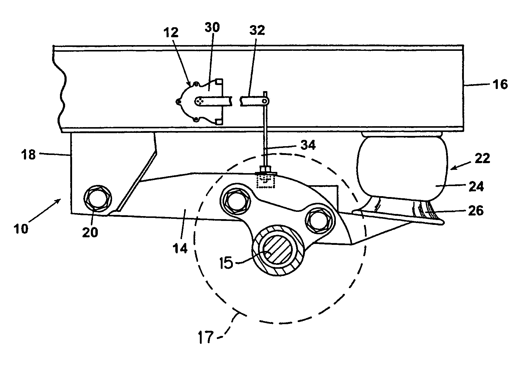
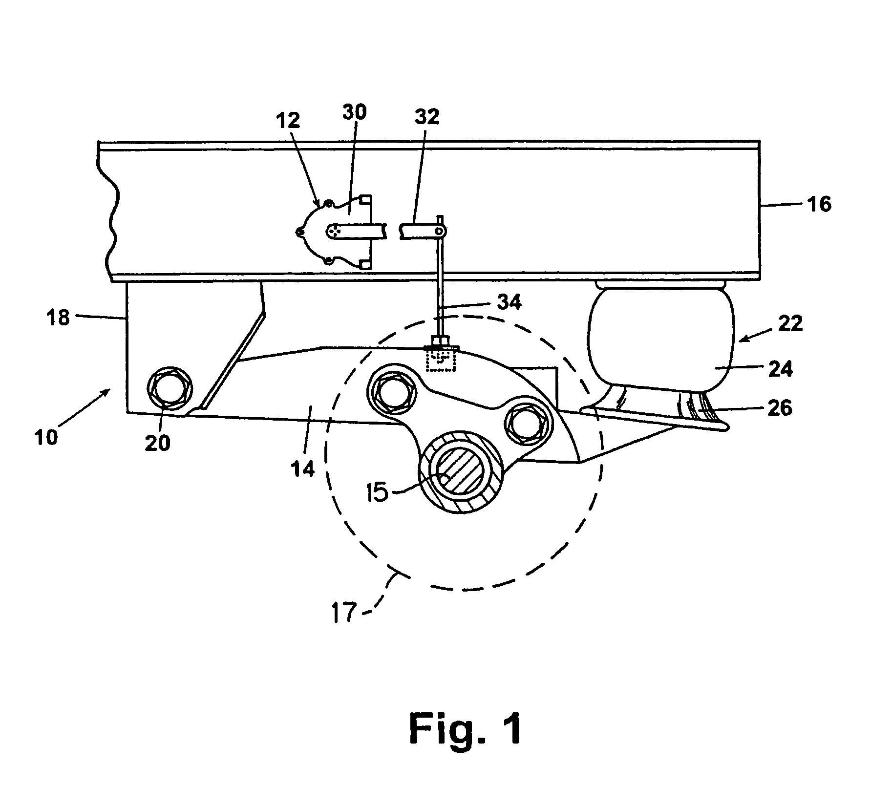
[0039]FIG. 1 illustrates a trailing arm suspension 10 in combination with a height control valve 12 according to the invention. The trailing arm suspension 10 comprises a trailing arm 14 having a first end that is pivotally connected to the vehicle frame 16 through a hanger bracket 18. Attached to trailing arm 14 is axle 15 to which ground engaging wheel 17 is attached (shown as a dashed line). Preferable, the pivotal connection is an elastomeric bushing 20.

[0040]An air spring 22 comprising a lift bag 24 and a piston 26 is positioned between the trailing arm 14 and the frame rail 16. The lift bag 24 is connected to the vehicle frame 16 and the piston 26 is connected to the trailing arm 14. Pressurized air can be introduced or exhausted from the lift bag to control the relative position of the vehicle frame 16 and the trailing arm 14. The lift bag 24 serves to dampen the rotational movement of the trailing arm 14 about the pivotal connection 20 with the vehicle frame.

[0041]Referring ...


PUM


Abstract

A height control valve for controlling the relative height between a vehicle frame and a trailing arm suspension. The height control valve comprises a housing defining an interior chamber and having an inlet port fluidly connecting to a source of pressurized air. An air spring port is provided in the housing for fluidly connecting to an air spring. Additionally, an exhaust port is provided in the housing for fluidly connecting to the atmosphere. A valve is disposed within the interior chamber and is selectively operable between a fill position, an exhaust position, and a neutral position.

Description

[0001]This application is a continuation of pending International Application No. PCT / US00 / 23278 filed Aug. 24, 2000, which designates the United States and claims priority benefits of U.S. Provisional Patent Application Ser. No. 60 / 150,621 filed Aug. 24, 1999.BACKGROUND OF THE INVENTION[0002]1. Field of the Invention[0003]The invention relates to a trailing arm suspension for a vehicle; and, more particularly, to a height control valve for controlling the ride height of the suspension relative to the vehicle.[0004]2. Description of the Related Art[0005]Trailing arm suspensions are well known and are commonly used in heavy-duty vehicles, such as semi-tractor / trailer configurations. The trailing arm suspension comprises opposing trailing arm assemblies mounted on opposite sides of the vehicle, preferably the vehicle frame rails. Each of the trailing arm assemblies includes a trailing arm having one end pivotally connected to a hanger bracket suspended from the frame rail. The other e...

Claims


Application Information

Patent Timeline
IPC IPC(8): B60G17/00B60G17/052F15B13/04
CPCB60G17/0525F15B13/0406B60G2200/31B60G2202/152Y10S267/01B60G2300/026B60G2500/202B60G2204/1482
Inventor PLATH, VICTOR A.
Owner HALDEX BRAKE
Learn More