Apparatus and method for aligning and fixing ribbon on a solar cell

Inactive Publication Date: 2006-10-05
KOMAX HOLDING
View PDF3 Cites 25 Cited by
  • Summary
  • Abstract
  • Description
  • Claims
  • Application Information

AI Technical Summary

Benefits of technology

[0011] One feature of the invention is avoiding the above identified problems when aligning and fixing a ribbon, i.e. the problem wh

Problems solved by technology

Misalignment of the ribbon relative to the bus bar causes power output losses and is not aesthetically pleasing.
Therefore, ribbon alignment on the front of the solar cell is of great importance and has been a difficult challenge for many machines to accomplish.
The difficulty is typically associated with the “flimsy” nature of the ribbon in its free state as well as camber problems with ribbon.
With th

Method used


Image

  • Apparatus and method for aligning and fixing ribbon on a solar cell
  • Apparatus and method for aligning and fixing ribbon on a solar cell
  • Apparatus and method for aligning and fixing ribbon on a solar cell

Examples


Embodiment Construction

[0029] A preferred embodiment is detailed below as well as various exemplary embodiments.

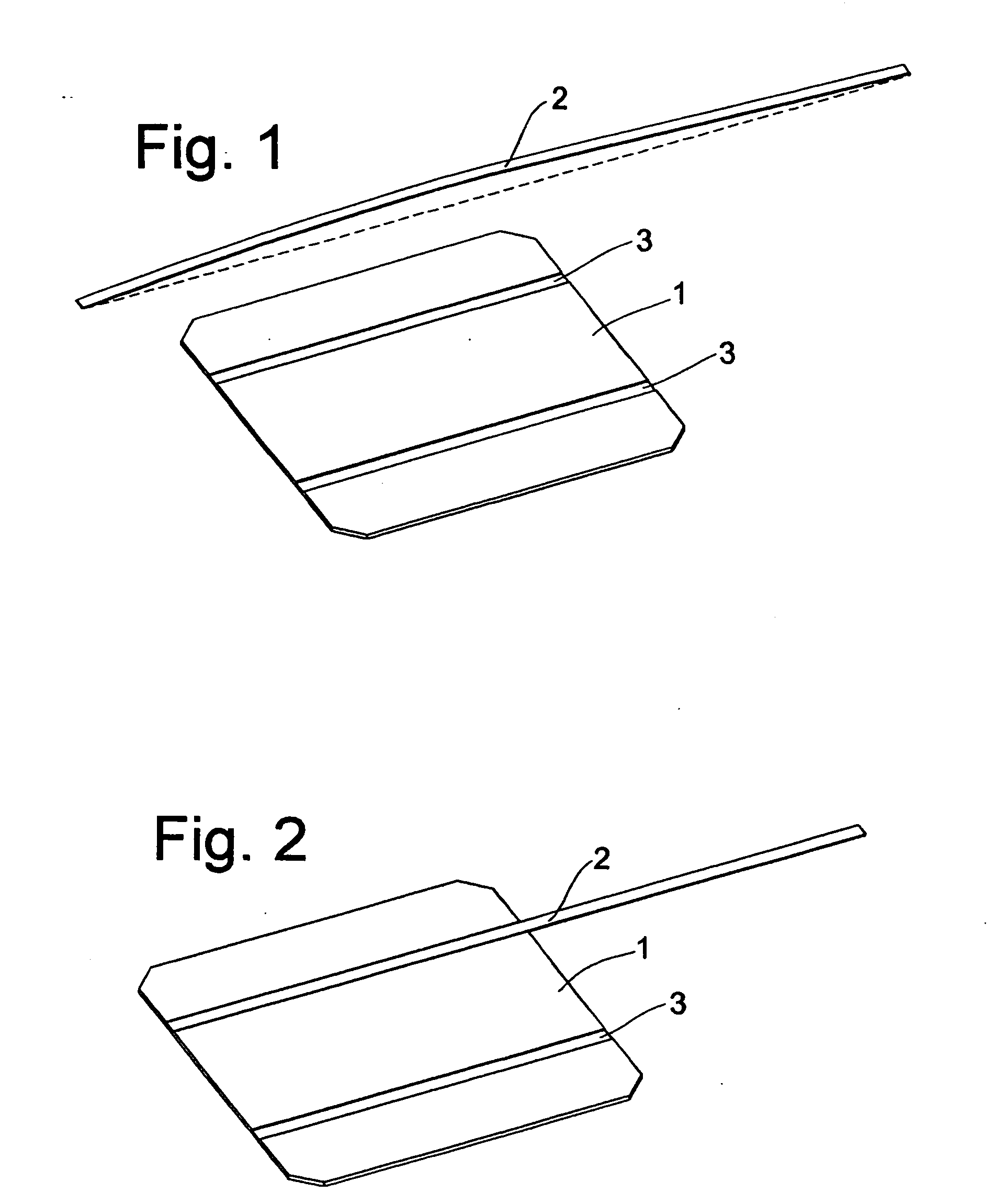
[0030] In FIG. 1 a solar cell 1 is prepared for the insertion of the ribbon 2 into the groove 3. The ribbon is a pre-tinned conductor belt which is fixed on the solar cell 1 by heating. Heating can be done either conventional or by radiation like laser light or by any other appropriate means. In order to have an optimal fixing the ribbon 2 should be really inserted in the grove 3.

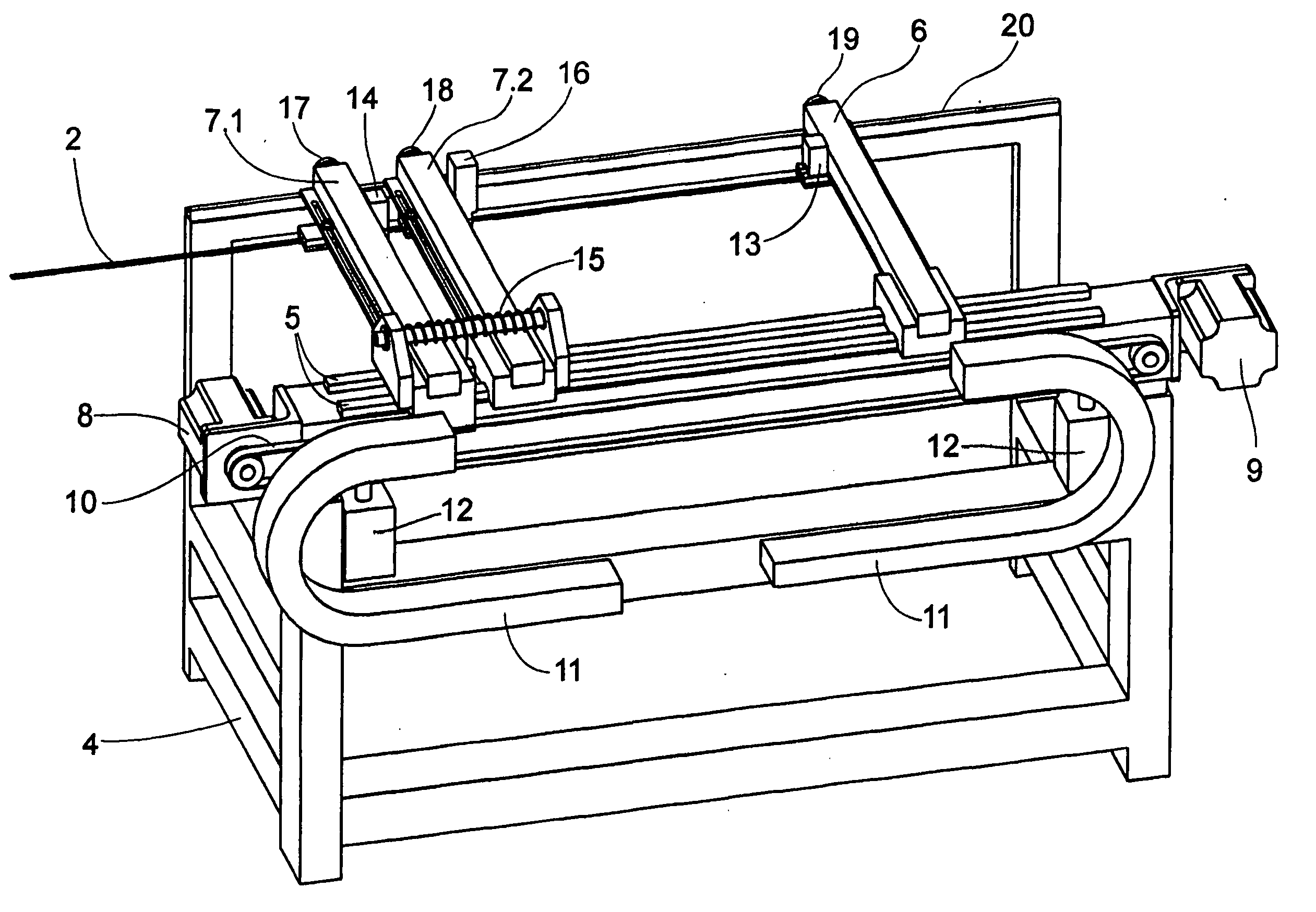
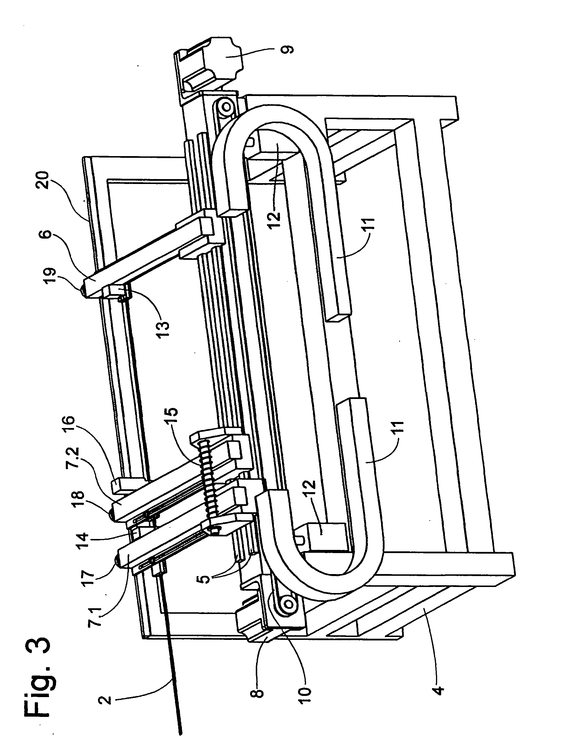
[0031] The apparatus according to FIG. 3 comprises a frame 4 with a linear guide 5, on which linear guide 5 a leading arm 6 and-according to the preferred embodiment-two trailing arms 7.1 and 7.2 are mounted. A servo motor 9 is provided to move the leading arm 6 along linear guide 5. Alternatively, the movements of the leading arm can be performed by a linear motor (not shown). A servo motor 8 is provided for the movement of the trailing arm 7.1 along linear guide 5. Each reference 10 refers to a belt and 11 refers to...


PUM

PropertyMeasurementUnit
Heataaaaaaaaaa
Tensionaaaaaaaaaa

Abstract

An apparatus and a method are proposed for aligning and fixing a ribbon onto the groove of a solar cell for avoiding undue stress on the ribbon as well as crystal damage of the solar cells by hardening of the ribbon. The apparatus includes a frame, a leading arm, and a trailing arm, the leading and trailing arms being movably mounted on at least one linear guide arranged on said frame. The apparatus further provides for upward and downward movement of the at least one linear guide, and a shear for cutting said ribbon. Both the leading arm and the trailing arm have a gripper for gripping the ribbon. These grippers are provided to apply a predetermined longitudinal tension to the ribbon when the leading and trailing arms are moved relative to one another.

Description

CROSS-REFERENCE TO RELATED APPLICATIONS [0001] This Application claims the benefit under Title 35, United States Code, §119(e) of U.S. Provisional Application No. 60 / 654,004, filed Feb. 18, 2005, the subject matter of which is incorporated herein by reference.BACKGROUND OF THE INVENTION [0002] 1. Field of the Invention [0003] This invention relates to a method for aligning and fixing a ribbon on a solar cell in order to facilitate forming a solar panel typically comprising several solar cells. In particular, the invention is related to such a method, wherein the ribbon is a pre-tinned metal ribbon. Furthermore, the invention is related to a solar cell on which an above-mentioned ribbon is fixed. [0004] 2. Related Art [0005] In the Photovoltaic industry, crystalline solar panels are made by interconnecting individual solar cells together in a line to form a complete circuit. The back of one cell is electrically connected to the front of the next. This process, known as stringing, is ...

Claims


Application Information

Patent Timeline
IPC IPC(8): B32B37/00
CPCH01L31/188Y02E10/50Y10T156/1322Y10T156/1052Y10T156/1744Y10T156/17Y10T156/12H01L31/022425
Inventor MICCICHE, BRIAN S.
Owner KOMAX HOLDING
Why Eureka
Try Eureka