
Wave-shape extendible door

A telescopic door and wave-shaped technology, applied in the field of wave-shaped telescopic doors, can solve the problems of poor decoration and appreciation, lack of shape changes and dynamics, and unsightly appearance, and achieve strong dynamics and shape changes, and are highly ornamental and attractive. decorative effect

Inactive Publication Date: 2007-03-28
HONGMEN ADVANCED TECH CORP
View PDF0 Cites 1 Cited by
  • Summary
  • Abstract
  • Description
  • Claims
  • Application Information

AI Technical Summary

Problems solved by technology

When this kind of telescopic door is unfolded, what people see from the front and rear sides of the door are the front and rear frames of each door frame and the intersecting tubes arranged crosswise. Each door frame is only in a single translation state, lacking in shape changes and dynamics, so the decoration and appreciation are poor
In addition, the wires connecting the power supply and the machine head of the existing telescopic door all pass through each door frame nakedly from the rear end of the telescopic door to the front end to connect with the control circuit installed in the machine head. Obviously, this connection method is neither beautiful nor Safety
Since telescopic doors are mostly used in streets and public places, how to make them satisfy the telescopic function and have poor decorative and ornamental properties has become an objective demand.

Method used


Image

  • Wave-shape extendible door
  • Wave-shape extendible door
  • Wave-shape extendible door

Examples


Embodiment 1

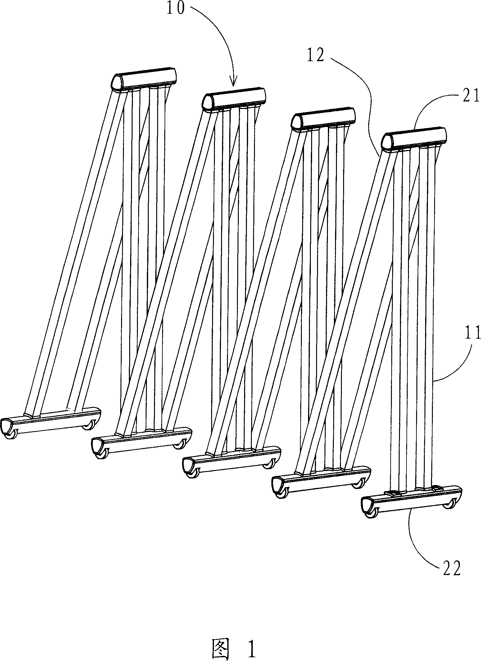
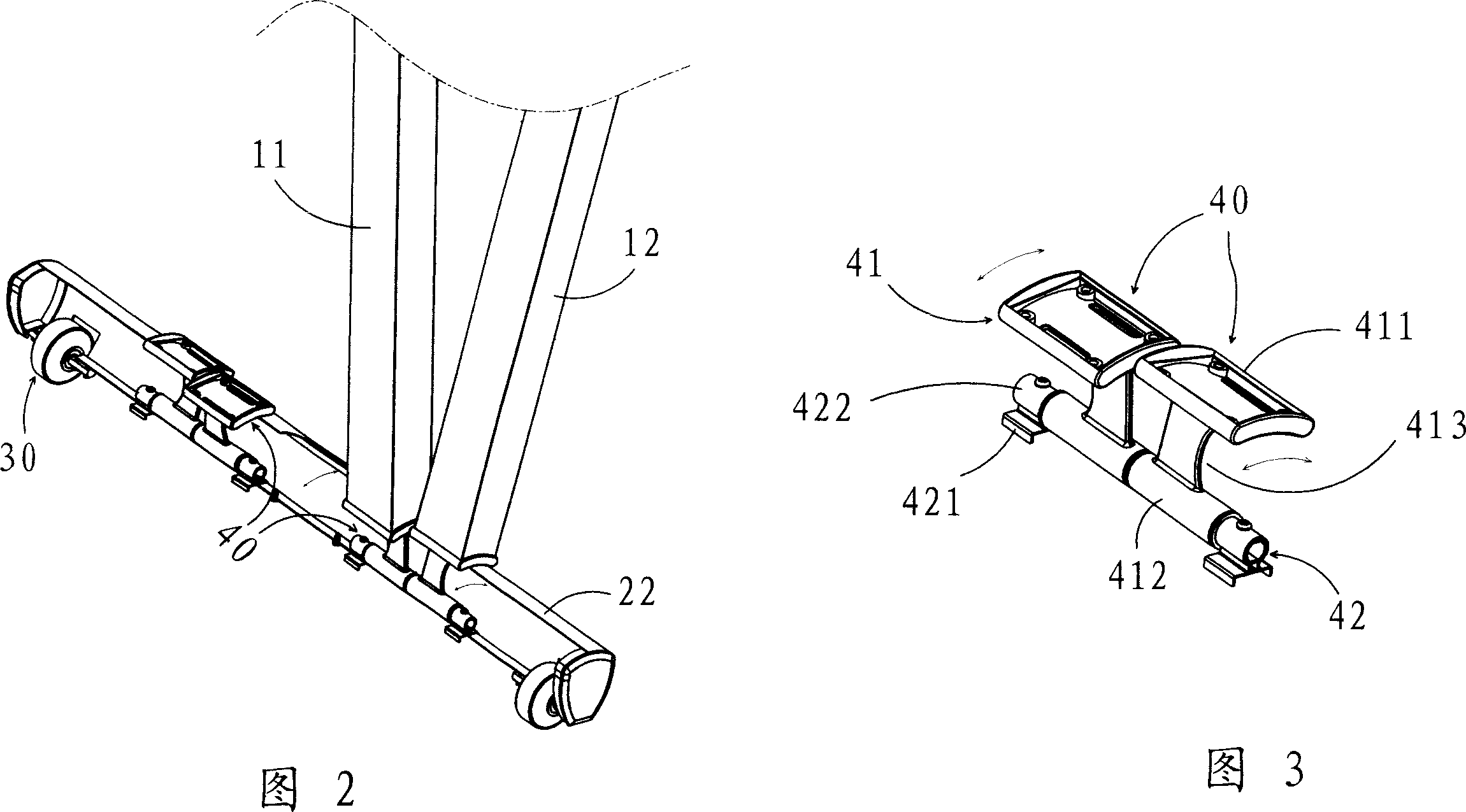
[0028] Referring to Fig. 1, the wave-shaped telescopic door is hinged with a plurality of upper beams 21 and lower beams 22 respectively at the upper and lower ends end-to-end to form a wave-shaped telescopic door when unfolded. Each group of door frames 10 is composed of an independent inner frame 11 and an outer frame 12, each of which is composed of two hollow tubular bodies, and the distance between the two outer frames 12 is the width of the door frame 10. The two ends of each inner frame and outer frame are respectively hinged with an upper crossbeam 21 and a lower crossbeam 22 through a hinge 40, and the upper crossbeam 21 and the lower crossbeam 22 are also hollow tubular bodies, and the lower pipe wall and the upper crossbeam The upper tube wall of the lower beam is provided with an upper through hole (not shown in the figure) and a lower through hole 221 (see FIG. 4 ) for the hinge 40 to rotate therein. The hinge structure of the inner and outer frames and the upper ...

Embodiment 2

[0032] This example shows another embodiment of the invention.

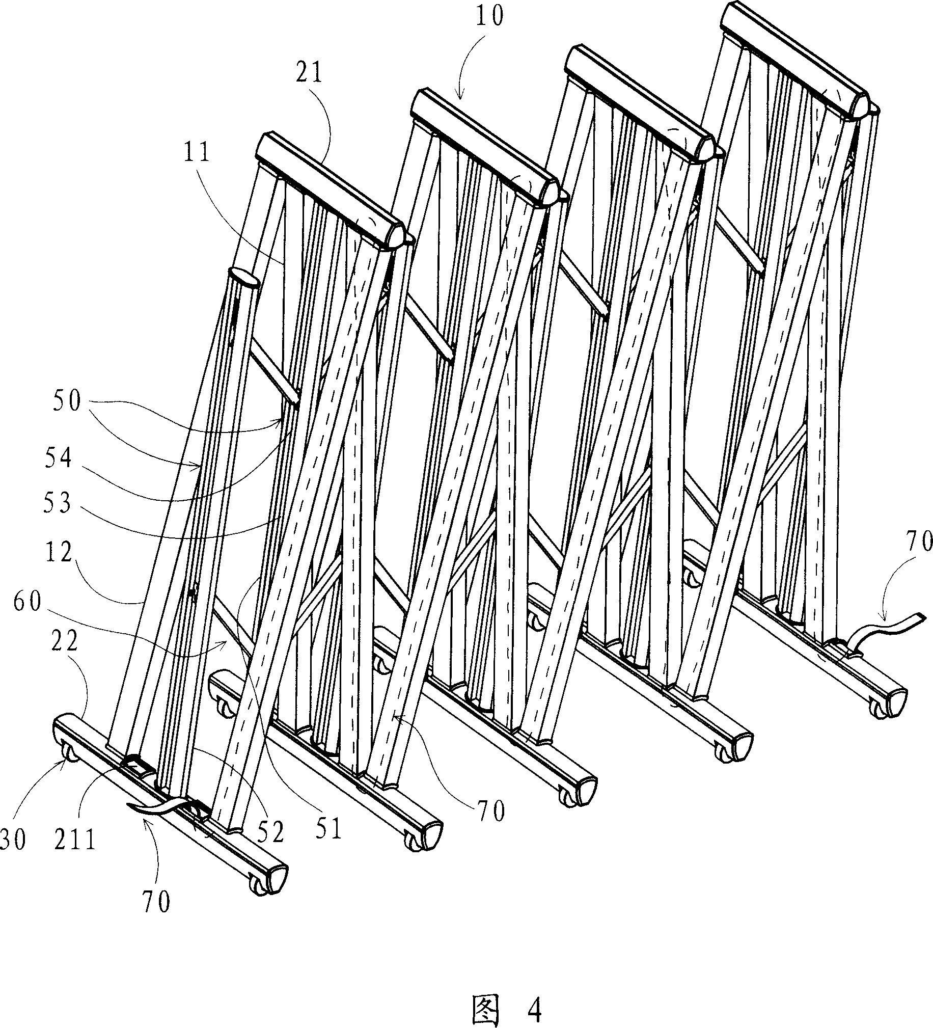
[0033] The basic structure is the same as in Embodiment 1, the difference is that on the basis of Embodiment 1, a column 50 is fixedly connected to each upper beam 21 and the center of the lower beam 22, and the upper and lower layers of movable crossings are arranged between each column. The pipes 60 are connected, and the specific structure is shown in Fig. 4 to Fig. 6 . As shown in Figure 4 and Figure 6, the column 50 includes an upper column 51 and a lower column 52. There are screw fixing slots. Upper column 51 is fixed on the upper beam 21 center between the inner frame 11 of door frame 10, and lower column 52 is fixed on the lower beam 22 of the inner frame 11 center of door frame 10, as shown in Figure 7, the lower end of the upper column and the upper end of the lower column for the free end. Among Fig. 5, the lower end of the lower column 52 is provided with a decoration cover 55, and the lower colum...


PUM


Abstract

The invention relates to a wave form stretching door that is made up of plural doorframes, plural upper beams and plural down beams. Each group of doorframe includes inner frame and external frame. The upper and down ends of the inner frame and down frame are hinged to upper beam and down beam. At least two wheels are installed on the each down beam. When the door stretches, the inner frame and external frame take reverse and level moving around the axis of upper beam and down beam. When the door shrinks, the inner frame and external frame take opposite direction rotating and level moving around the axis of upper beam and down beam. The invention has strong moving effect.

Description

【Technical field】 [0001] The invention relates to a door opened in a telescopic manner, in particular to a wave-shaped telescopic door which is wave-shaped when opened. 【Background technique】 [0002] The electric telescopic door is a new type of door that is driven by a motor and opened or closed in a telescopic manner. It is widely used because of its convenient opening, beautiful appearance, and electric control. The basic structure of the existing electric telescopic door includes the head part and the telescopic door part connected with it, wherein the telescopic door part is formed by hinged with a plurality of rectangular or arched door frames and their horizontal axes through the upper and lower cross-type connecting rods. Each door frame is set upright and arranged in parallel at a certain distance. When the telescopic door is opened and closed, each door frame moves in parallel in the same direction through the walking wheels at the bottom of the door frame. When ...

Claims


Application Information

Patent Timeline
IPC IPC(8): E06B11/02
Inventor 余家红
Owner HONGMEN ADVANCED TECH CORP
Learn More