Backlight including external electrode fluorescent lamp and method for driving the same

a fluorescent lamp and backlight technology, which is applied in the direction of lighting and heating equipment, instruments, process and machine control, etc., can solve the problems of inability to connect the ccfls in parallel arrangement and drive the backlight using a conventional inverter, and the edge light type is not suitable for a large screen panel. achieve the effect of high luminance and efficiency

Inactive Publication Date: 2004-01-06
KWANG WOON DISPLAY TECH
View PDF20 Cites 102 Cited by
  • Summary
  • Abstract
  • Description
  • Claims
  • Application Information

AI Technical Summary

Benefits of technology

The present invention provides external electrode fluorescent lamps capable of obtaining high luminance and efficiency using a low frequency of 100 kHz or lower.

Problems solved by technology

In particular, the edge light type is not suitable for a large screen panel as the luminance of the panel is weak even though the CCFL itself is highly luminescent.
In the direct light type, it is impossible to connect the CCFLs in parallel arrangement and drive the backlight using a conventional inverter as the distance between the CCFLs has to be provided within a limited screen space to achieve desired illumination.
As a result, the weight of the lamp tend to increase.
In addition, in the conventional flat-fluorescent lamp, partitions and spacers in the form of a bead or cross are typically interposed between the upper and lower substrates in order to enlarge a screen area; thus, a uniform luminance cannot be achieved as the striped patterns of the partitions appear on the screen.
Although the EEFL tends to have a longer operation life than the CCFL, it has not been widely accepted as a backlight source due to the EMI and low efficiency.
Furthermore, the EEFL has not been employed as a backlight source as its luminance and efficiency tend to be low as the LC-resonance type inverter designed for driving the CCFL is used for driving the EEFL.
However, there are some drawbacks in that a uniform and thin panel cannot be realized due to a decrease in the luminance of the electrode portion.
In addition, the high frequency driving causes the undesirable EMI to be emitted, thus the efficiency of the electrodes becomes low.
Furthermore, the high frequency power source is undesirable in designing a compact device using such a power source.
However, the bonded portions of the electrodes can be easily damaged since coefficient of the thermal expansion of the glass tubes is different from that of the metal.
However, it is difficult to apply this type of structure to manufacture a fine tube to be used in a compact device.
On the other hand, it is impossible to connect the CCFLs in parallel arrangement and drive the CCFLs using a single inverter.
However, the sine waves generated by an inverter and used for driving the CCFLs cannot efficiently control the wall charges; thus, it produces much lower luminance and efficiency than that of the EEFL having a single tube.
In addition, when a plurality of EEFLs interconnected in parallel are driven by a single inverter, the number of active lighting EEFLs is limited as the time period to which a high voltage is applied during one cycle is limited.
Therefore, a uniform luminance cannot be realized when a number of the EEFLs are disposed in a plane as a backlight source.
As mentioned above, even if the EEFLs can be driven by the LC-resonance type inverter of several ten kHz to drive the CCFL, the backlight consists of the EEFL cannot be efficiently realized.

Method used


Image

  • Backlight including external electrode fluorescent lamp and method for driving the same
  • Backlight including external electrode fluorescent lamp and method for driving the same
  • Backlight including external electrode fluorescent lamp and method for driving the same

Examples


second embodiment

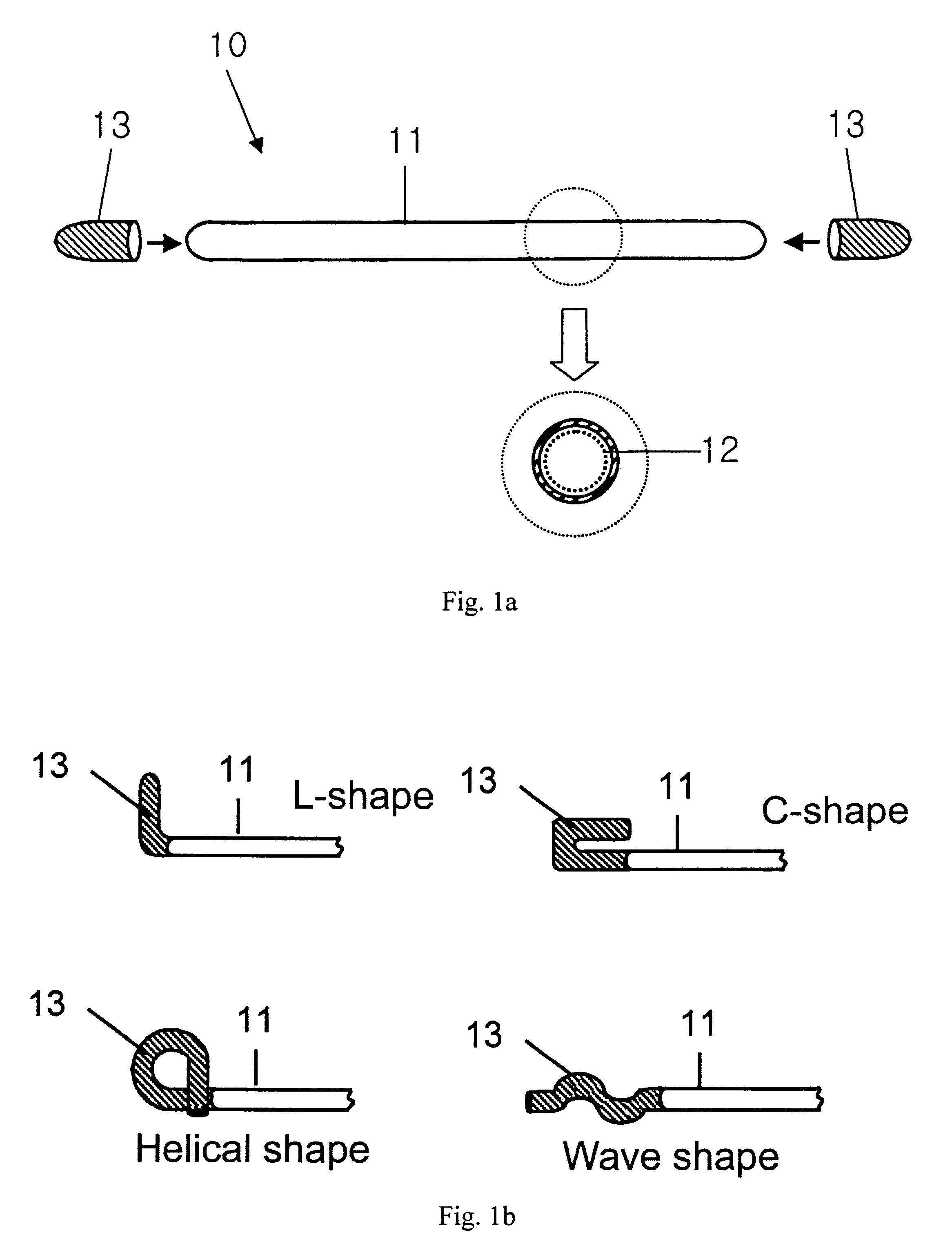
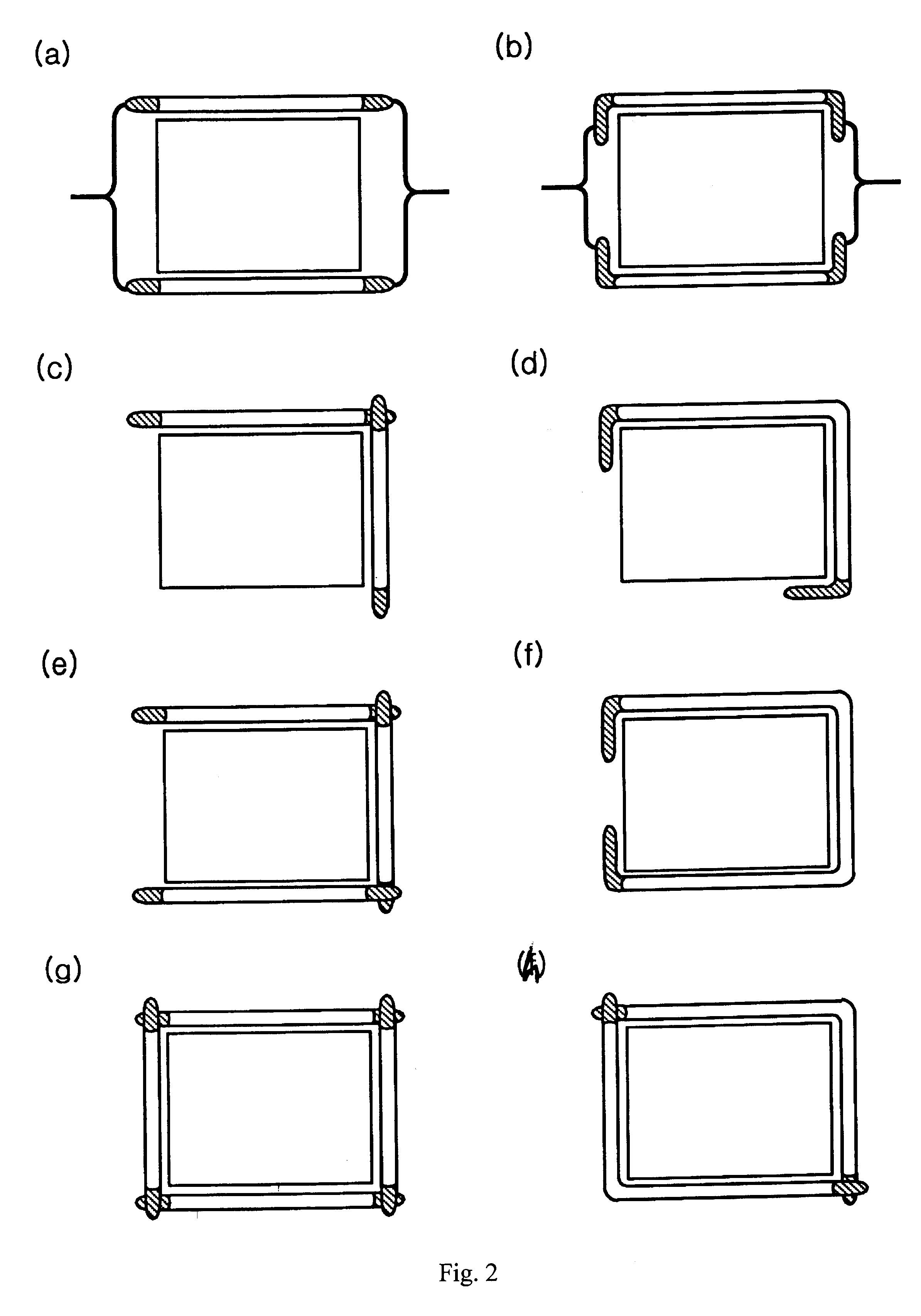
FIG. 2 shows different forms of edge backlight sources according to the present invention. As shown in FIG. 2, the EEFLs may be disposed around the plastic light guide in various formats. The edge active lighting type electrode can be employed as the external electrode fluorescent lamp and the cold cathode fluorescent lamp since high luminance and high efficiency can be realized using the electrode structures, as shown in FIG. 1. To this end, the inventive lamps are disposed at the edge portions of the plastic light guide and driven by a single inverter. The inventive lamps may be installed on both ends or along all edge portions of the plastic light guide.

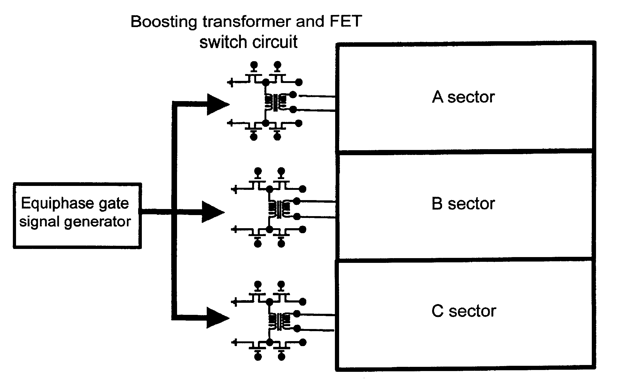
FIG. 3 shows different direct light arrangements of the EEFLs according to the second embodiment of the present invention. The present invention is characterized in that high luminance and high efficiency are achieved by driving the parallel-connected EEFLs by a means of the switching inverter. The fine tube having an outer diamet...

third embodiment

FIG. 6a shows the backlight 30 according to the present invention, and FIG. 6b shows the assembled state of the backlight 30 shown in FIG. 6a. Referring to FIGS. 6a and 6b, the backlight 30 includes an upper substrate 31 and a lower substrate 32 distanced a part by a predetermined amount. The bottom surface of the upper substrate 31 is formed of an upper layer 33 of fluorescent substance. The top surface of the lower substrate 32 is also formed with a lower layer 34 of fluorescent substance.

A plurality of fluorescent lamps 35 is installed at a predetermined interval above the lower substrate 32. The fluorescent lamps 35 serve to support the upper and lower substrates 31 and 32 when coupled, and simultaneously, serve as a partition therebetween. The external electrodes 36 made of electrically conductive material are installed at both ends of the outer peripheral surface of each fluorescent lamp 35.

In order to supply the backlight 30 with electrical power, an upper electrode 37 and a ...


PUM


Abstract

The present invention discloses a backlight including external electrode fluorescent lamps and a method for driving the backlight. The backlight includes fluorescent lamps having external electrodes made of an electrically conductive material for wrapping the outer peripheral surfaces including edge cross-sections on both ends of a glass tube with a layer of fluorescent substance applied thereon. The backlight is constructed in a manner that a plurality of such fluorescent lamps are installed at the outer portions of a plastic light guide, and an alternating current type power source is applied from the outside to the fluorescent lamps by installing a plurality of the fluorescent lamps between a reflecting plate and a diffusing plate and electrically connecting them with one another. The backlight of the present invention is driven by a square wave from a switching inverter, and is characterized by the use of an overshooting waveform and a self-discharge effect favorable to an initial discharge, thereby driving it using a low frequency of several dozen kHz and thus realizing high luminance and high efficiency.

Description

1. Field of InventionThe present invention relates to a fluorescent lamp with external electrodes and a backlight luminaire, and more particularly, to an improved backlight including an external fluorescent lamp in which the external electrodes are installed at both ends of the fluorescent lamp, and a method for driving the backlight.2. Background of InventionIn general, a flat panel display is categorized into two types: an active lighting type and a passive lighting type. The active lighting type includes a flat panel cathode-ray tube, a plasma display panel, an electronic active lighting element, a fluorescent display, an active lighting diode, etc., where as the passive lighting type includes a liquid crystal display.In the liquid crystal display, an image is formed not by a self-illumination provided by the incident light from the outside of the liquid crystal panel. To accomplish this, a backlight luminaire is typically installed at the rear end of the liquid crystal panel to ...

Claims


Application Information

Patent Timeline
Patent Type & Authority Patents(United States)
IPC IPC(8): H01J61/00H01J61/72H01J65/04H05B41/28H05B41/24
CPCH01J61/72H01J65/046H05B41/24H05B41/2806H01J61/305Y02B20/22Y02B20/00
Inventor CHO, GUANG-SUPCHOI, EUN-HA
Owner KWANG WOON DISPLAY TECH
Why Eureka
Try Eureka