Generator with utility fault ride-through capability

a technology of utility faults and generators, applied in the direction of electric generator control, emergency power supply arrangements, machines/engines, etc., can solve the problems of difficult control of the dc bus, disruption of power to large regions, and much more serious stability problems, and achieve the effect of simplifying the generator torque command approach

Inactive Publication Date: 2005-06-09
UNITED TECH CORP
View PDF7 Cites 99 Cited by
  • Summary
  • Abstract
  • Description
  • Claims
  • Application Information

AI Technical Summary

Benefits of technology

[0018] This invention has the advantage that the generator is completely decoupled from the grid (and its disturbances) by the total converter. The partial converter system, by contrast, is not completely decoupled, as the stator is directly connected to the utility grid, and grid disturbances cause large transients which cannot be buffered or decoupled by the converter.
[0019] This invention has the advantage that in the system provides utility disturbance and fault ride through ability via a robust current reference synthesis function and simplified generator torque command approach.
[0020] This invention has the advantage that in the system provides synthesizing of the three-phase current references from a single sensed phase.
[0021] This invention has the advantage that in the system provides operat

Problems solved by technology

Faults can be caused by at least one phase conductor being inadvertently connected to ground (a ground fault), or the inadvertent connection, or short circuiting of multiple phase conductors.
The reason for this requirement is straight forward; if wind generated power is at a high level of penetration, and a momentary fault occurs, the dropping of the significant amount of wind generated power (as required under the old operating rules) can cause much more serious stability problems, such as frequency swings, or large system wide instabilities of generation systems.
These are very extensive fault conditions and can lead to the disruption of power to large regions, effecting large numbe

Method used


Image

  • Generator with utility fault ride-through capability
  • Generator with utility fault ride-through capability
  • Generator with utility fault ride-through capability

Examples


Embodiment Construction

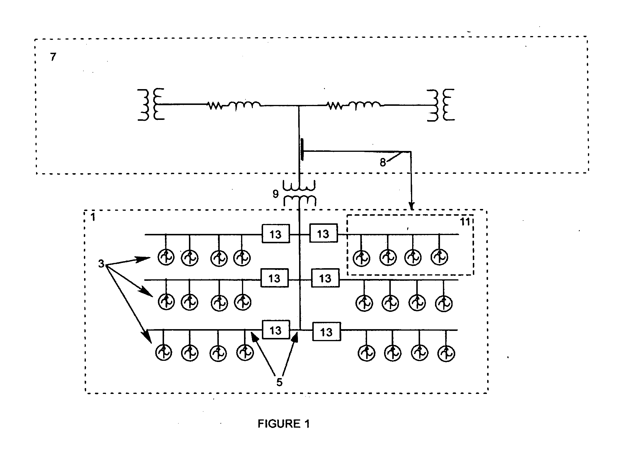
[0030] Refer to FIG. 1, which shows a collection of generators with current regulated inverter systems in the form of a wind or water current energy farm 1. Individual wind turbines 3 are connected to a wind farm collection system 5. The energy farm collection system 5 may interface with a utility grid distribution, sub-transmission, or transmission system 7 via a substation transformer 9. The energy farm collection system 5 may isolate wind turbine groups 11 using sectionalizing devices 13. The sectionalizing devices, often circuit breakers or fuses, isolate a group of turbines 11 in case of an electrical fault within the turbine group 11, thus allowing the rest of the windfarm 1 to continue operating. Groups of turbines (such as 11) are connected in common to the energy farm collection system 5 for interfacing with utility grid 7.

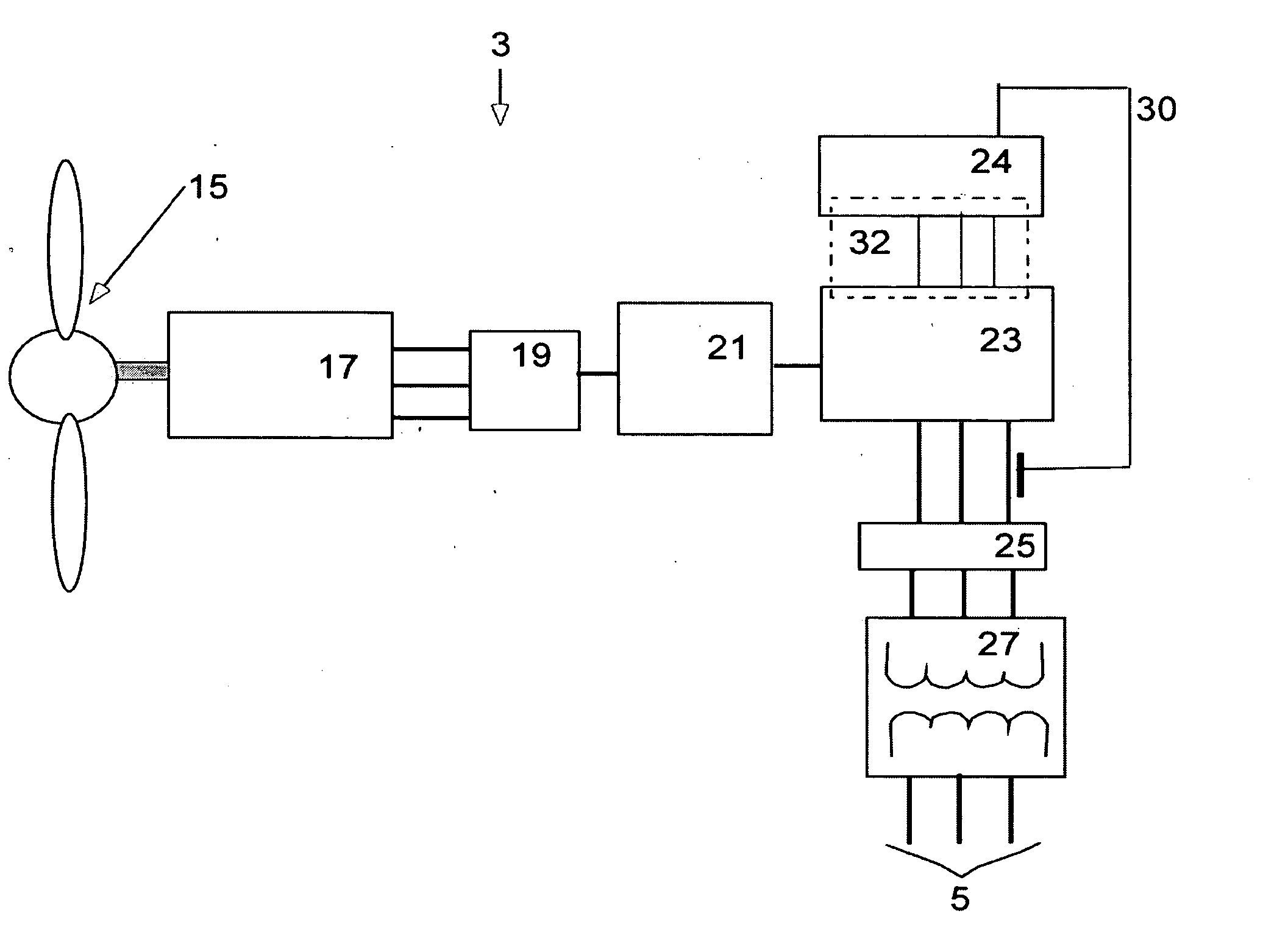
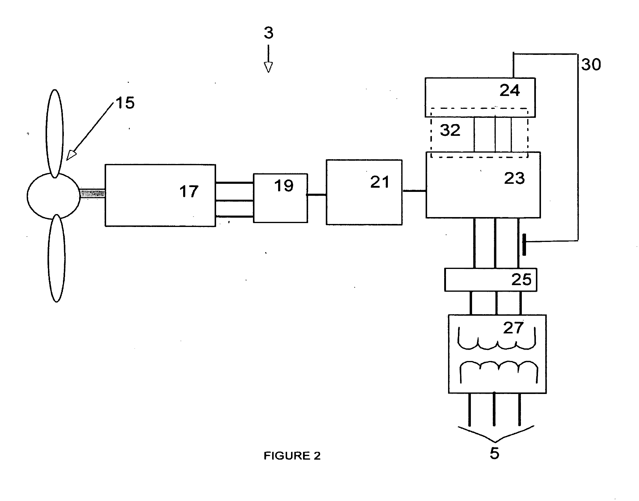
[0031] The energy farm 1 is made up of fluid-flow turbines 3, shown in detail in FIG. 2. Each fluid-flow turbine has a rotor 15. An output of the rotor ...


PUM


Abstract

A wind powered turbine with low voltage ride-through capability. An inverter is connected to the output of a turbine generator. The generator output is conditioned by the inverter resulting in an output voltage and current at a frequency and phase angle appropriate for transmission to a three-phase utility grid. A frequency and phase angle sensor is connected to the utility grid operative during a fault on the grid. A control system is connected to the sensor and to the inverter. The control system output is a current command signal enabling the inverter to put out a current waveform, which is of the same phase and frequency as detected by the sensor. The control system synthesizes current waveform templates for all three-phases based on a sensed voltage on one phase and transmits currents to all three-phases of the electrical system based on the synthesized current waveforms.

Description

CROSS-REFERENCE TO REALTED APPLICATIONS [0001] This application is a Continuation In Part of co-pending U.S. patent application Ser. No. 10 / 773,851 which was filed on Feb. 4, 2004 and which claimed priority under 35 U.S.C. § 119(e) to U.S. Provisional Patent Application No. 60 / 468,899 Variable Speed Wind Turbine Technology which was filed on May 7, 2003 and which is incorporated herein by reference. [0002] This application is related to U.S. Pat. No. 6,304,002; U.S. patent application Ser. No. 10 / 213,764 of Amir S. Mikhail and Edwin C. Hahlbeck entitled “Improved Distributed Power Train That Increases Electric Power Generator Density” filed Aug. 7, 2002; U.S. patent application Ser. No. 09 / 920,247 of Peter Stricker, entitled “Distributed Generation Drivetrain (DGD) Controller For Application To Wind Turbine And Ocean Current Turbine Generators” filed Jul. 31, 2001; U.S. patent application Ser. No. 10 / 426,287 Kevin L. Cousineau: Distributed Static Var Compensation (DSVC) System For W...

Claims


Application Information

Patent Timeline
IPC IPC(8): F03D7/02F03D7/04F03D9/00H02H7/06H02P9/00H02P9/02H02P9/04H02P11/00
CPCF03D7/0224H02P2101/15F03D7/0284F03D7/048F03D9/002F03D9/003F03D9/005F05B2210/16F05B2270/1032F05B2270/337H02J2003/001H02P9/02H02P9/04H02P9/10H02P9/102H02P9/105H02P9/107Y02E10/723Y02E10/725Y02E10/763Y02E20/16H02J3/383H02J3/386H02J3/387Y02E10/563H02J3/382H02P2101/10F03D7/0272F03D9/25F03D9/255F03D9/257H02J3/001H02J2300/40H02J2300/30H02J2300/28H02J2300/20H02J3/381Y02E10/76Y02E10/72
Inventor ERDMAN, WILLIAMCOUSINEAU, KEVIN L.MIKHAIL, AMIR S.
Owner UNITED TECH CORP
Why Eureka
Try Eureka