
System and method for a primary feedback switched mode power supply

a switched mode and power supply technology, applied in the field of power conversion, can solve the problems of difficult to compete with switching mode power supply, circuits are higher cost, poor regulation, etc., and achieve the effects of reducing electromagnetic interference emissions

Active Publication Date: 2007-06-14
ACTIVE SEMI
View PDF8 Cites 104 Cited by
  • Summary
  • Abstract
  • Description
  • Claims
  • Application Information

AI Technical Summary

Benefits of technology

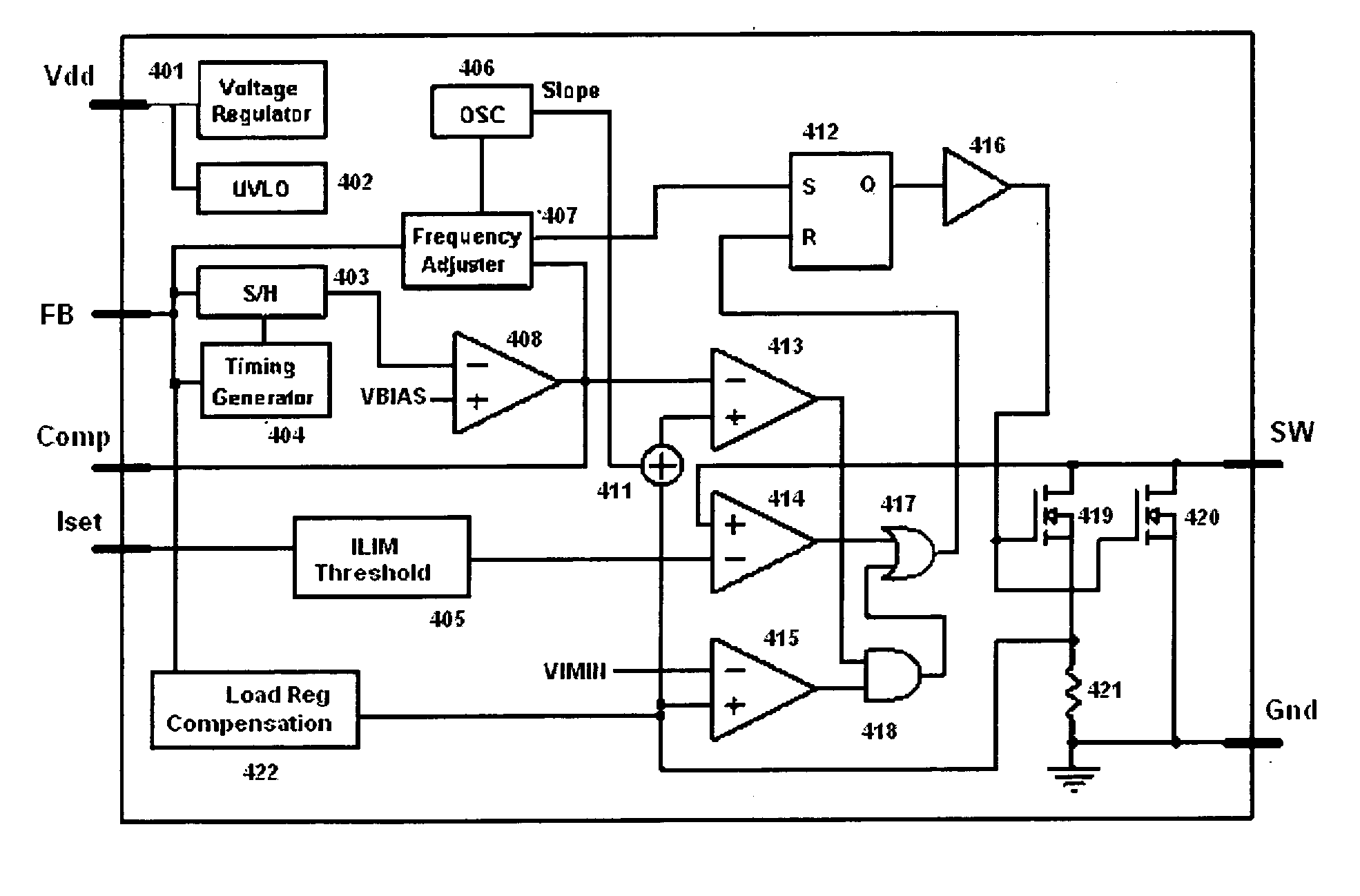
[0023] In another embodiment, primary side controlled power converter is described having a voltage sensing means for sensing a transformer output voltage, a primary switching means for controlling energy in a primary winding of the transformer, a feedback means for generating an error signal, and a control means for controlling the error signal to the primary switching means wherein the primary switching means controls the transformer and thereby regulates an output of the power converter. A further embodiment includes a frequency adjusting means for adjusting the system frequency in response to the feedback signal. Another embodiment has a driver means for modulating rise and fall times of the primary switching means for reducing electromagnetic interference emissions.

Problems solved by technology

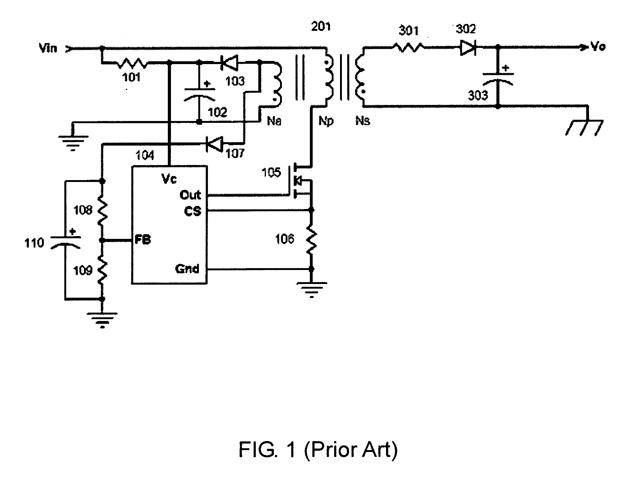
Even though the linear power supply is low in cost, it becomes very difficult to compete with switching mode power supplies because of its heavy weight and low efficiency.
However, the regulation becomes very poor when loading drops below 10% of its rated load.
The main disadvantage of this circuit is higher cost.
The additional components and a safety approved optical coupler add significant cost to the overall design.
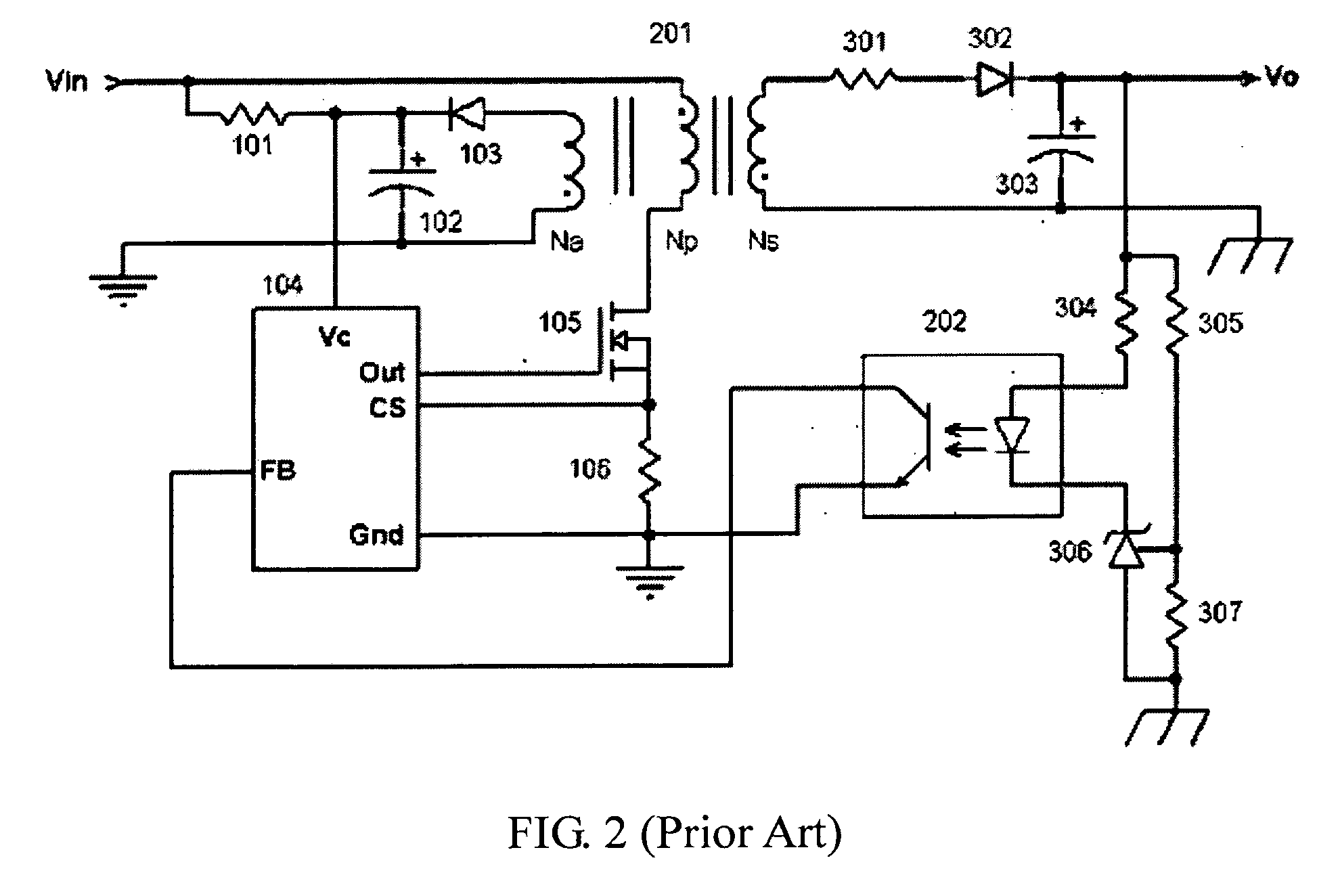
The main disadvantage of this circuit is high cost.
The IC 306 and the safety approved optical coupler 202 significantly increases the cost of type of converter.

Method used


Image

  • System and method for a primary feedback switched mode power supply
  • System and method for a primary feedback switched mode power supply
  • System and method for a primary feedback switched mode power supply

Examples


Embodiment Construction

[0030] The present invention is best understood by reference to the detailed figures and description set forth herein.

[0031] Embodiments of the invention are discussed below with reference to the figures. However, those skilled in the art will readily appreciate that the detailed description given herein with respect to these figures is for explanatory purposes as the invention extends beyond these limited embodiments. For example, it should be appreciated that those skilled in the art will, in light of the teachings of the present invention, recognized a multiplicity of alternate and suitable approaches, depending upon the needs of the particular applications to implement the functionality of any given detail described herein, beyond the particular implementation choices in the following embodiments described and shown. That is, there are numerous modifications and variations of the invention that are too numerous to be listed but that all fit within the scope of the invention. Al...


PUM


Abstract

A primary side controlled power converter having a voltage sensing means coupled to a transformer of the power converter and configured to provide a voltage feedback waveform representative of an output of the transformer is provided. A primary switching circuit operates to control energy storage of a primary side of the transformer. The primary switching circuit is operable during an on time and inoperable during an off time. The on and off time is switched at a system frequency. A feedback amplifier generates an error signal indicative of a difference between the voltage feedback waveform and a reference voltage. A sample and hold circuit samples the error signal at a periodic frequency during the off time. An error signal amplifier is configured to provide the sampled value to the primary switching circuit wherein the primary switching circuit controls the transformer and thereby regulates an output of the power converter.

Description

CROSS-REFERENCE TO RELATED APPLICATIONS [0001] The present Utility patent application claims priority benefit of the U.S. provisional application for patent Ser. No. 60 / 748,132 filed on Dec. 7, 2005 under 35 U.S.C. 119(e). The contents of this related provisional application are incorporated herein by reference for all purposes. FEDERALLY SPONSORED RESEARCH OR DEVELOPMENT [0002] Not applicable. REFERENCE TO SEQUENCE LISTING, A TABLE, OR A COMPUTER LISTING APPENDIX Not applicable. COPYRIGHT NOTICE [0003] A portion of the disclosure of this patent document contains material that is subject to copyright protection. The copyright owner has no objection to the facsimile reproduction by anyone of the patent document or patent disclosure as it appears in the Patent and Trademark Office, patent file or records, but otherwise reserves all copyright rights whatsoever. FIELD OF THE INVENTION [0004] This invention relates generally to the field of power conversion and, more particularly, to sw...

Claims


Application Information

Patent Timeline
IPC IPC(8): H02M3/335
CPCH02M3/33507
Inventor HUYNH, STEVENCHEN, MINGLIANGYU, MINGFAN
Owner ACTIVE SEMI
Learn More