
Pocket mouth pipe edges sewing machine

A sewing machine and hemming technology, which is applied to sewing machine components, program-controlled sewing machines, sewing machine control devices, etc., can solve the problem of not being able to form the cutting seam of the center cutter correctly, and achieve the effect of improving the correctness.

Active Publication Date: 2012-07-04
JUKI CORP
View PDF1 Cites 0 Cited by
  • Summary
  • Abstract
  • Description
  • Claims
  • Application Information

AI Technical Summary

Problems solved by technology

[0011] Therefore, there is a disadvantage that the slit of the center knife cannot be accurately formed with respect to the slit of the corner knife.

Method used


Image

  • Pocket mouth pipe edges sewing machine
  • Pocket mouth pipe edges sewing machine
  • Pocket mouth pipe edges sewing machine

Examples


Embodiment Construction

[0049] (The overall structure of the embodiment of the invention)

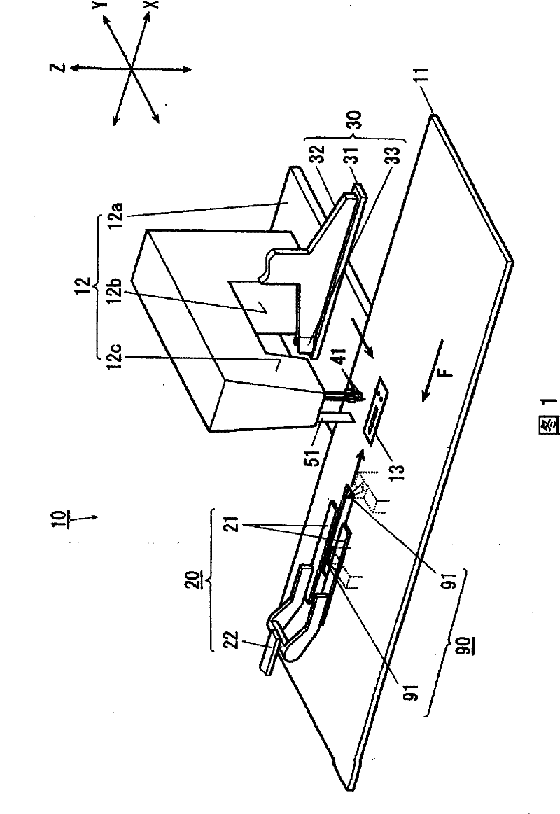
[0050] Below, refer to Figure 1~Figure 17 The bag hemming sewing machine 10 according to the embodiment of the present invention will be described. figure 1 It is a perspective view showing a schematic structure of the entire bag-mouth piping sewing machine 10. In addition, in this embodiment, each direction is determined on the basis of the XYZ axis shown in each figure, and the Z axis direction is consistent with the vertical movement direction of the center cutter described later, and the plane of the sewing industry is the same as the Z axis direction. Perpendicular, the direction in which the cloth is fed parallel to the work plane is referred to as the X-axis direction, and the direction parallel to the work plane and perpendicular to the X-axis direction is referred to as the Y-axis direction.

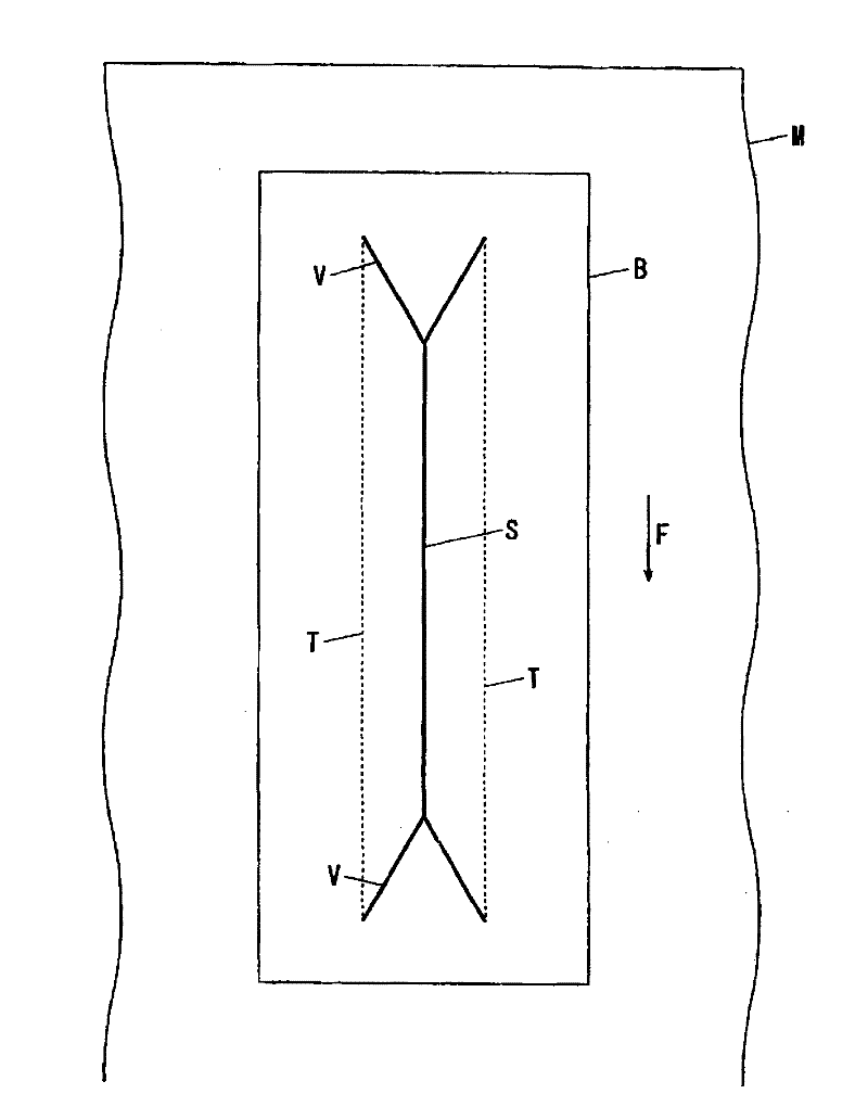
[0051] The bag hemming sewing machine 10 uses two parallel stitches T formed by double needles 41 and 41 to sew ...


PUM


Abstract

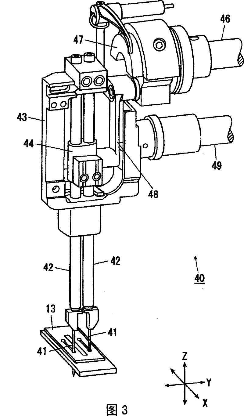
The present invention provides a pocket mouth pipe edges sewing machine comprising a needle vertical movement mechanism 40 having two sewing needles 41; a binder 30 for guiding a binding cloth B, while allowing the cloth to move along; a cloth feeding mechanism 20 for allowing a feeding driving means 23 to feed a body fabric M and the binding cloth; a center knife mechanism 50 for elevating / lowering the center knife 51 with a knife driving means 57 and forming the linear cut S; a corner knife mechanism 90 for forming the V shape cuts at both the ends of a linear seam; setting input means 855,86 for performing a setting input to determine a sewing finish position and a cut finish position by the center knife; and an operation control means 80 for controlling an additional cut operation bydriving the cloth feeding mechanism and the center knife mechanism after the end of sewing when a distance L2 from the cut finish position to the sewing finish position is shorter than a distance D1 from the center knife to each sewing needle.

Description

Technical field [0001] The present invention relates to a sewing machine for forming pockets on a sewn object. Background technique [0002] The conventional bag hemming sewing machine has a cloth feeding mechanism that conveys the garment part fabric and piping fabric (hereinafter, the garment part fabric and piping fabric are collectively referred to as fabric) along the binder, and moves the two needles up and down to move the fabric to be transported. The needle up and down movement mechanism that forms two parallel stitches on the upper and lower stitches moves the center cutter up and down and makes the blade part and the fixed cutter fixed on the needle plate slide in contact with each other. A center cutter mechanism that forms a linear slit on the cloth, and a corner cutter mechanism that moves the corner cutter up and down to form a V-shaped slit at both ends of the slit formed by the center cutter. [0003] Moreover, in the above-mentioned center knife mechanism, since ...

Claims


Application Information

Patent Timeline
Patent Type & Authority Patents(China)
IPC IPC(8): D05B3/10D05B37/00
CPCD05B3/24D05B19/12D05B21/00D05B35/02D05B37/04D05B69/10D05B69/30
Inventor 植田昌彦戌亥优北田贤治
Owner JUKI CORP
Learn More