

Self-lubricator of ball leading lever
A ball screw and self-lubricator technology, applied in the field of self-lubricators, can solve problems such as wear, more serious wear, damage, etc., and achieve the effect of increasing lubrication and smooth transmission
- Summary
- Abstract
- Description
- Claims
- Application Information
AI Technical Summary
Problems solved by technology
Method used
Image

Examples
Embodiment Construction
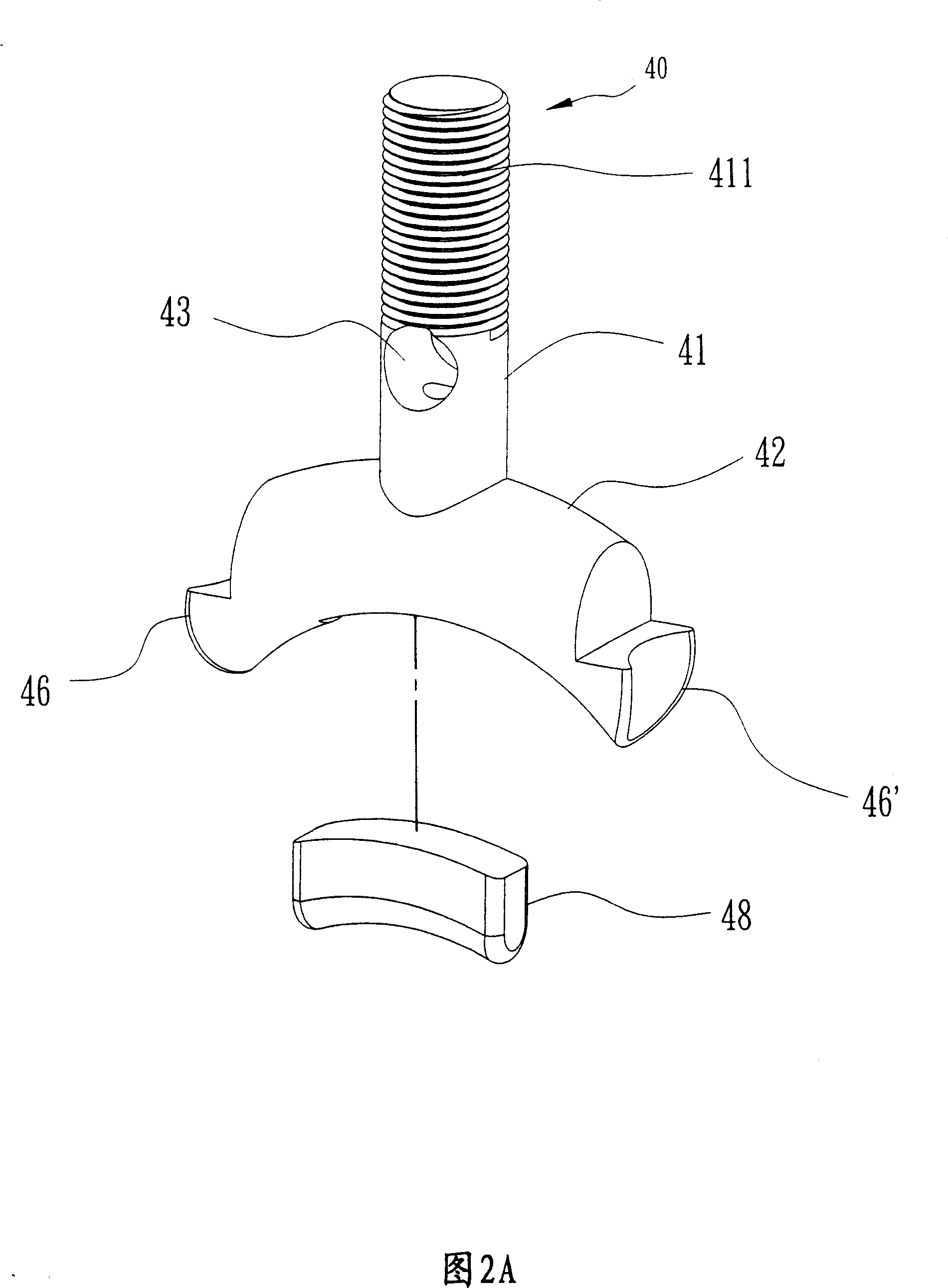
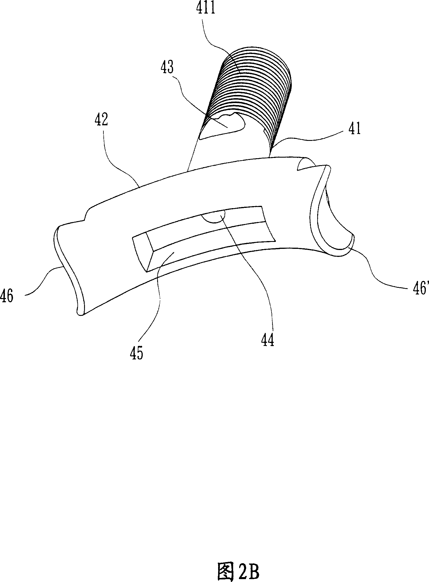
[0038] Please refer to Fig. 2A, 2B and shown in Fig. 3, it is the first embodiment of the self-lubricating device 40 of the present invention, the self-lubricating device 40 of this embodiment is generally an inverted T-shaped body, and its longitudinal end forms a fixed rod 41, its transverse end forms an arc-shaped steering rod 42; the upper half of the fixed rod 41 is provided with an external threaded portion 411, and its middle position is provided with an oil hole 43, and the inside of the fixed rod 41 is from the oil hole 43 toward Down to the rotating rod 42, an oil seepage hole 44 is provided; Hole 45, an oil-absorbing member 48 can be placed in this cavity 45, and the bottom end of the oil-absorbing member 48 is slightly protruded from the cavity 45; The turning part 46 and the second turning part 46', the side end surfaces of the two turning parts 46, 46' form a circular arc concave surface; the oil absorbing member 48 can absorb lubricating oil and can store and re...
PUM
 Abstract
Description
Claims
Application Information