
Zoom lens and image pickup apparatus

A zoom lens and lens group technology, applied in image communication, television, optics, etc., can solve the problem of full length

Inactive Publication Date: 2007-04-04
KONICA MINOLTA OPTO
View PDF1 Cites 5 Cited by
  • Summary
  • Abstract
  • Description
  • Claims
  • Application Information

AI Technical Summary

Problems solved by technology

[0004] However, the zoom lens disclosed here has a small zoom ratio of about 3 to 5 times, and there is a problem that the overall length is too long for the zoom ratio.

Method used


Image

  • Zoom lens and image pickup apparatus
  • Zoom lens and image pickup apparatus
  • Zoom lens and image pickup apparatus

Examples


Embodiment 1

[0141] [Specification]

[0142] Focus distance: f=6.49mm~14.46mm~43.16mm

[0143] Picture angle: 2ω=60.6°~27.2°~9.2°

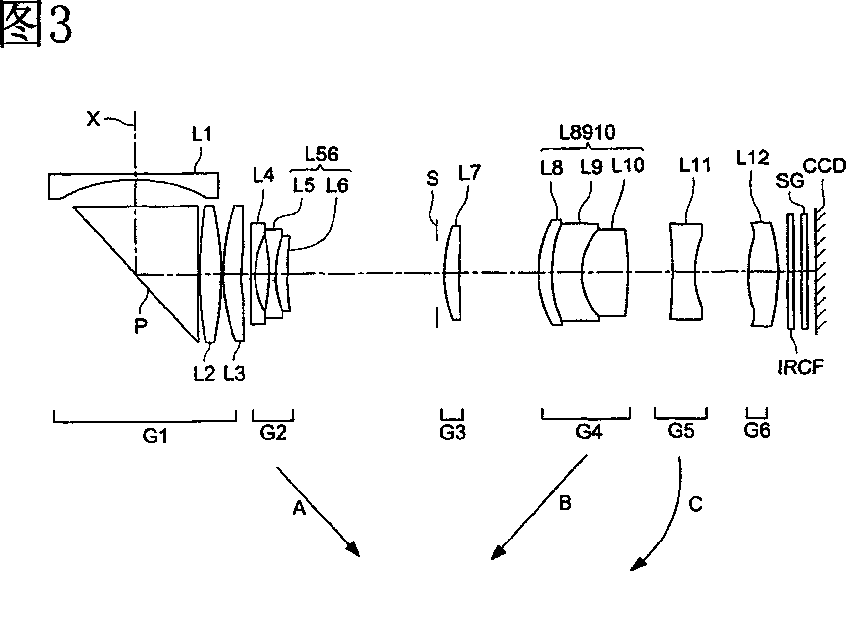
[0144] Table 6 shows the lens data of the zoom lens in Example 1. In addition, FIG. 3 shows a cross-sectional view of the zoom lens in Example 1, and FIGS. 4(A) to (C) show the spherical aberration, astigmatism, and distortion aberration of the zoom lens in Example 1. picture. Here, FIG. 4(A) is an aberration diagram at a focal distance of 6.49 mm. FIG. 4(B) is an aberration diagram at a focal length of 14.46 mm. FIG. 4(C) is an aberration diagram of a focal distance of 43.16 mm. In addition, in the following aberration diagrams, the solid line in the spherical aberration diagram indicates the d-line, the dotted line indicates the g-line, the solid line in the astigmatism diagram indicates the sagittal image plane, and the dotted line indicates the meridional plane image plane.

[0145] (Table 6)

[0146] i

ri

di

ndi

...

Embodiment 2

[0172] [Specification]

[0173] Focus distance: f=6.49mm~16.74mm~43.16mm

[0174] Picture angle: 2ω=60.7°~23.6°~9.2°

[0175] Table 7 shows the lens data of the zoom lens in Example 2. In addition, FIG. 5 shows a cross-sectional view of the zoom lens in Example 2, and FIGS. 6(A) to (C) show spherical aberration, astigmatism, and distortion aberrations of the zoom lens in Example 2. picture. Here, FIG. 6(A) is an aberration diagram at a focal distance of 6.49 mm. FIG. 6(B) is an aberration diagram at a focal length of 16.74 mm. FIG. 6(C) is an aberration diagram at a focal distance of 43.16 mm.

[0176] (Table 7)

[0177] i

ri

di

ndi

νdi

1

2

3

4

5

6

7

8

9

10

11

12

13

14

15

16

17

18

19

20

21

22

23

24

25

26

27

28

29

79.192

17.666

50.126

-30.903

18.008

-574.171

-105.658

...

Embodiment 3

[0203] [Specification]

[0204] Focus distance: f=6.45mm~16.65mm~42.85mm

[0205] Picture angle: 2ω=61.0°~23.6°~9.3°

[0206] Table 8 shows the lens data of the zoom lens in Example 3. In addition, FIG. 7 shows a cross-sectional view of the zoom lens in Example 3, and FIGS. 8(A) to (C) show the spherical aberration, astigmatism, and distortion aberration of the zoom lens in Example 3. picture. Here, FIG. 8(A) is an aberration diagram at a focal distance of 6.45 mm. FIG. 8(B) is an aberration diagram at a focal distance of 16.65 mm. FIG. 8(C) is an aberration diagram at a focal distance of 42.85 mm.

[0207] (Table 8)

[0208] i

ri

di

ndi

νdi

1

2

3

4

5

6

7

8

9

10

11

12

13

14

15

16

17

18

19

20

21

22

23

24

25

26

27

28

29

136.358

17.288

51.247

-31.347

23.375

-86.024

-103.634...


PUM


Abstract

The structure of the present invention is a zoom lens whose magnification is changed by moving a plurality of lens groups, and includes, in order from the object side along the optical axis, a zoom lens with positive refractive power, which is always positioned on the optical axis at the time of magnification and focusing. Fixed 1st lens group sum, 2nd lens group sum with negative refractive power, 3rd lens group sum with positive refractive power, 4th lens group sum with positive refractive power, 5th lens group with negative refractive power and, a sixth lens group having a positive refractive power, wherein the first lens group includes a reflective optical element having a function of deflecting the light path by reflecting light. In addition, focusing on an object with a limited distance is performed by at least the fifth lens group, and the focal length of the zoom lens and the lateral magnification of the lens group constituting the zoom lens satisfy certain conditions.

Description

technical field [0001] The present invention relates to a zoom lens and an imaging device for forming an optical image on a solid-state imaging element such as a CCD image sensor or a CMOS image sensor. Background technique [0002] In recent years, small digital cameras and video cameras equipped with solid-state imaging elements such as CCD (Charge Coupled Devices) type image sensors or CMOS (Complementary Metal-Oxide Semiconductor) type image sensors equipped with small imaging units, among them, with the solid-state imaging elements The high pixelation of high-resolution lenses has higher and higher requirements for high-variable zoom lenses with higher imaging performance. In addition, there is a demand for further miniaturization of zoom lenses for compact imaging devices. [0003] As a compact zoom lens for a compact imaging device, for example, Japanese Patent Application Laid-Open No. 2005-195757 discloses a first lens group with a positive refractive power, a seco...

Claims


Application Information

Patent Timeline
Patent Type & Authority Applications(China)
IPC IPC(8): G02B15/16G02B9/62G02B1/04H04N5/225
CPCG02B15/173G02B15/1461
Inventor 佐野永悟山下敦司
Owner KONICA MINOLTA OPTO
Learn More