
Disk driver

A technology of optical disc drive and optical disc, which is applied in the directions of instruments, optical recording/reproduction, head configuration/installation, etc., and can solve the problems that the Z-axis direction cannot be compensated normally.

Inactive Publication Date: 2007-04-04
LEJIN GUANGDIAN ELECTRONIC CO LTD SHANGHAI
View PDF0 Cites 0 Cited by
  • Summary
  • Abstract
  • Description
  • Claims
  • Application Information

AI Technical Summary

Problems solved by technology

[0010] However, the problem with the regulator 23 that provides the rotational driving force for the optical disc under the above-mentioned prior art conditions is that it only supports the tracking operation, and cannot normally compensate the Z-axis direction when the position changes due to the bending of the optical disc 10 or the influence of the surrounding environment. , that is, the focal point in the direction of the optical axis

Method used


Image

  • Disk driver
  • Disk driver
  • Disk driver

Examples


Embodiment Construction

[0040] Embodiments of the optical disc drive of the present invention will be described in detail below with reference to the accompanying drawings.

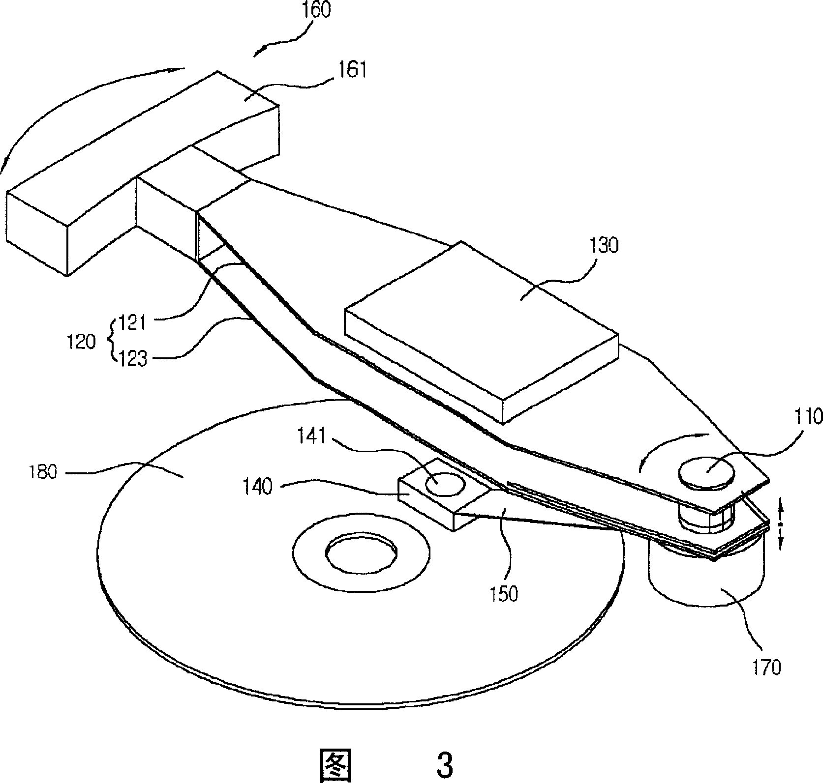
[0041] FIG. 3 is a perspective view of the optical disc drive of the present invention, and FIG. 4 is a front view of the optical disc drive of the present invention.

[0042] As shown in the figure, the optical disk drive of the present invention includes the following components: a rotating shaft 110, a rocker arm 120, an optical pickup module 130, a guide block 140, a suspension 150, an adjuster 160 for tracking servo, and an adjuster 170 for focus servo .

[0043] The above-mentioned rotating shaft 110 is vertically arranged on a base (not shown), and the rocker arm 120 is combined on the above-mentioned rotating shaft 110 .

[0044] The above-mentioned rocker arm 120 is rotatably coupled to the above-mentioned rotating shaft 110 and adjusted at a certain interval, and is composed of a pair of plates (upper and lower plates...


PUM


Abstract

This invention is a ROM driver with one end of the rocker rotate fixed to the rotating shaft, and the other end fixed the module of read / write model. The driver includes the following two parts: a focus serve adjuster fixed to the rotating end of the rocker; a tracing serve adjuster fixed to the other end of the rocker to supply driving power for crank motion of the rocker. With the focus serve fixed on the rotating shaft to adjust the focus point up and down, it is capable of accurately making up position change of the disk recording area at rotation.

Description

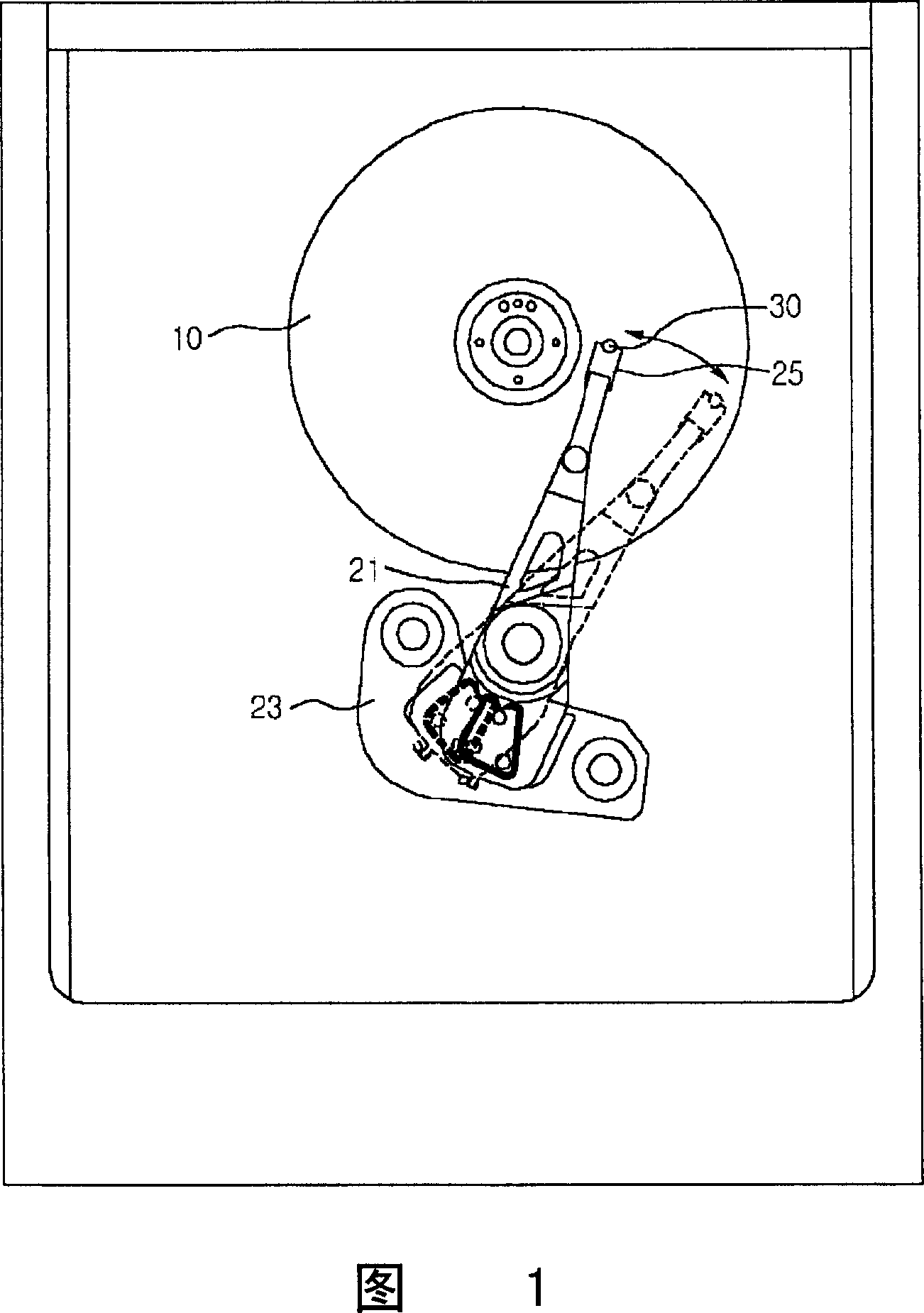
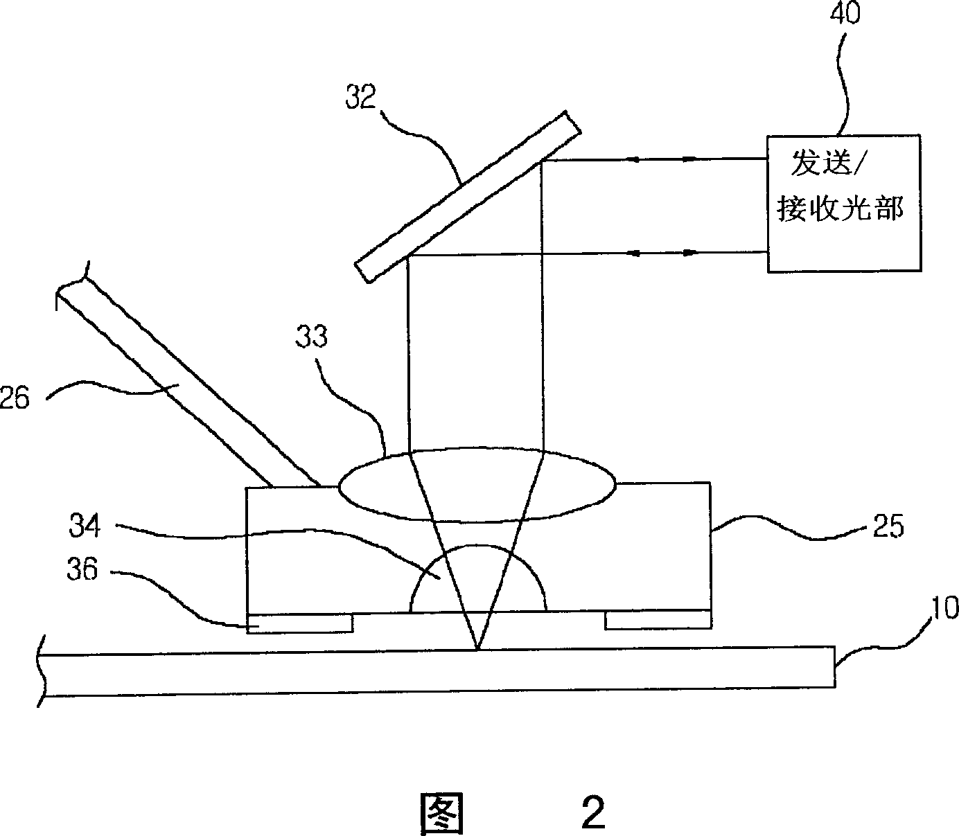
technical field [0001] The present invention relates to the technology of optical disc drive. Background technique [0002] 1 is a plan view of a conventional optical disc drive, and FIG. 2 is a schematic sectional view of a state in which a guide block of the conventional optical disc drive slides and drives the outer end of an optical disc. FIG. 2 is a schematic diagram of a device using a refractive solid immersion lens as the small lens 34 . [0003] As shown in the figure, the existing optical disc drive includes the following components: a rotatable rocker arm 21 arranged on the base of the optical disc drive (base); The end of the arm 21 can utilize hydrodynamic air pressure to float on the guide block 25 used to scan the track of the optical disc; it is arranged on the guide block 25 to form a light spot on the above-mentioned optical disc 10 for recording / reading optical information The optical magnetic head 30. [0004] The above-mentioned optical disk 10 includ...

Claims


Application Information

Patent Timeline
IPC IPC(8): G11B7/09G11B7/095
Inventor 金相天
Owner LEJIN GUANGDIAN ELECTRONIC CO LTD SHANGHAI
Learn More