
Lower structure of car body

A body, automobile technology, applied in the field of the lower body structure of automobiles

Inactive Publication Date: 2011-05-11
MAZDA MOTOR CORP
View PDF7 Cites 0 Cited by
  • Summary
  • Abstract
  • Description
  • Claims
  • Application Information

AI Technical Summary

Problems solved by technology

[0004]However, if the vehicle is a large vehicle, the size of the spare tire will also increase accordingly, so the storage volume of the spare tire room will also need to be increased, so that the spare tire room The bottom will protrude significantly downwards

Method used


Image

  • Lower structure of car body
  • Lower structure of car body
  • Lower structure of car body

Examples


Embodiment Construction

[0028] Hereinafter, embodiments of the present invention will be described with reference to the drawings.

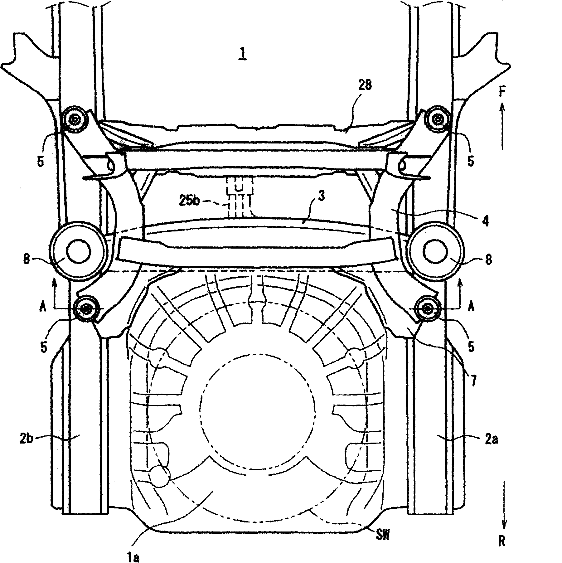
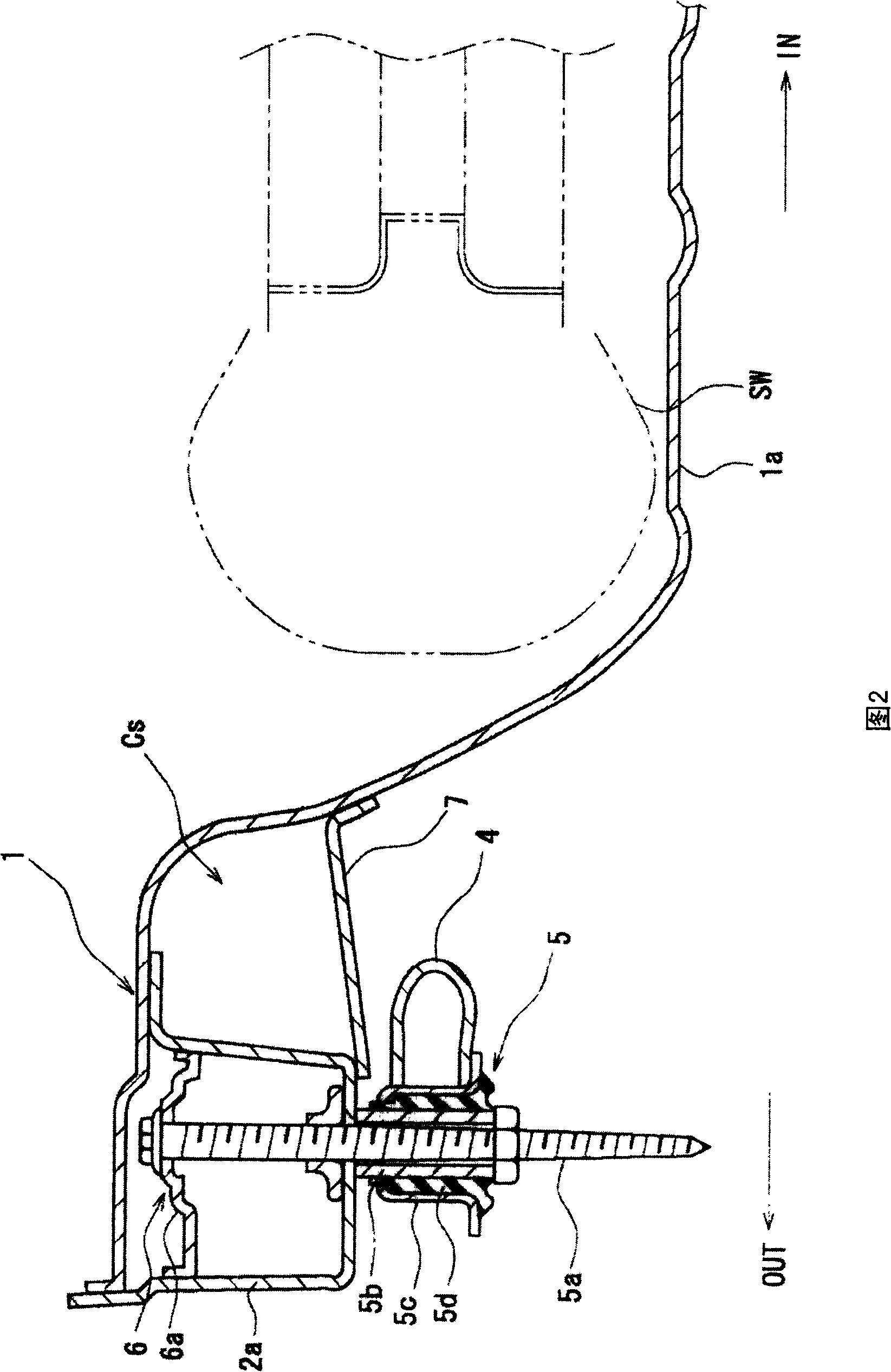
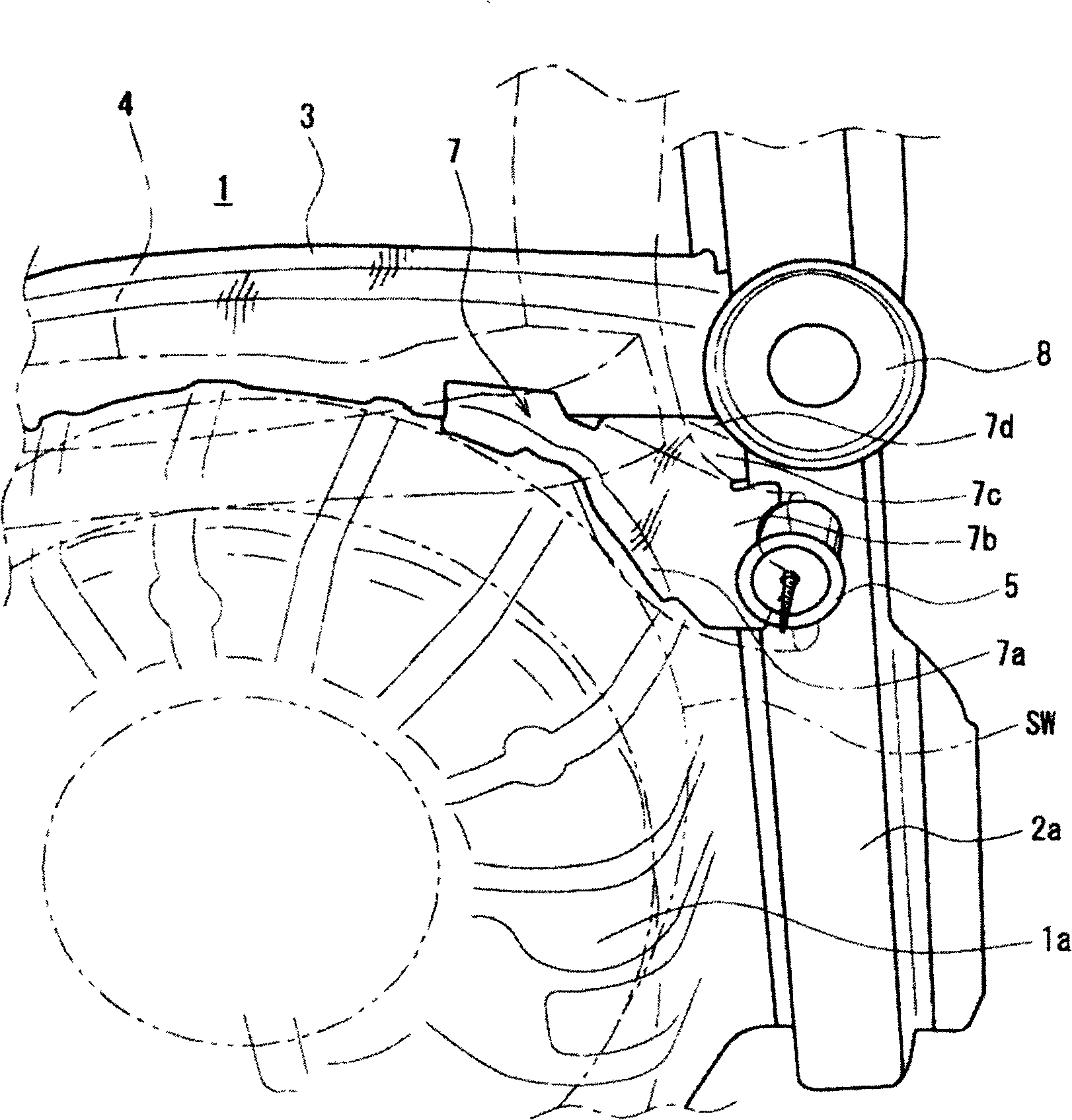
[0029] figure 1 It is a bottom view showing an automobile underbody structure according to an embodiment of the present invention. At the rear of the vehicle body, a part of the floor plate 1 is recessed downward to form a spare tire compartment 1a for accommodating a spare wheel SW. In addition, a pair of rear side members 2a, 2b extending in the front-rear direction of the vehicle body are provided below the left and right sides of the floor panel 1 .

[0030] The rear side members 2a, 2b are connected to each other at the front of the spare tire room 1a by interposing the first cross member 3 extending in the vehicle width direction between the rear side members 2a, 2b.

[0031] In addition, between the rear side members 2a and 2b, a sub-frame 4 composed of a substantially "well"-shaped frame (perimeter type frame) is provided, and the front and rear ends of the su...


PUM


Abstract

The present invention relates to a lower body structure for a vehicle, which includes a floor (1) of a spare tire pan (1a) depressing downwards, a pair of rear carlings (2a, 2b) disposed on the left / right side of the floor (1) and extending along the front / rear direction of the vehicle body, a beam (3) bridged between the pair of rear carlings (2a, 2b) in the front part of the spare tire pan (1a), a sub frame (4) at least a part of which is supported by a support part (5) of the rear side carlings (2a, 2b) at a rear position of the beam (3), and a junction panel (7) bridged between the end neighborhood of the beam (3), and the support part (5) of the sub frame (4) on the rear carlings (2a, 2b) and the spare tire pan (1a). By using the present invention, the simple structure can be used to efficiently improve the support rigidity of the sub frame by the support part, even layout is restricted by arrangement of the spare tire pan.

Description

technical field [0001] The present invention relates to an automobile lower body structure, comprising a bottom plate formed with a downwardly recessed spare tire pan, a pair of rear longitudinal beams arranged on the left and right sides of the bottom plate and extending along the front and rear direction of the vehicle body. The front part of the spare tire room is erected on the crossbeam between the pair of rear longitudinal beams, and the subframe is supported at least partly by the supporting part provided by the rear longitudinal beam at the rear position of the above-mentioned crossbeam. Background technique [0002] As the lower body structure of an automobile, it is known that mounting parts for mounting the sub-frame to the pair of left and right rear side members are provided on the left and right, and one end of each mounting part on the left and right passes in a substantially straight line below the spare tire compartment. In order to prevent the rear portion...

Claims


Application Information

Patent Timeline
Patent Type & Authority Patents(China)
IPC IPC(8): B62D25/20B62D23/00B62D21/11
Inventor 江岛胜美
Owner MAZDA MOTOR CORP
Learn More