
Remote control coaxial double rotor wing model helicopter balance mechanism

A balance mechanism and dual-rotor technology, applied in the field of aircraft, can solve the problems of poor stability, non-adjustable control system and high sensitivity of the control system of the remote control model helicopter

Inactive Publication Date: 2007-04-11
黄国川
View PDF0 Cites 2 Cited by
  • Summary
  • Abstract
  • Description
  • Claims
  • Application Information

AI Technical Summary

Problems solved by technology

[0002] The stability of remote control model helicopters is poor, and they have higher requirements for control technology. Compared with those who have mastered certain control skills, beginners have relatively different requirements for the balance performance of remote control model helicopters; beginners mainly The purpose is to fly the remote control model helicopter smoothly and safely, so the model helicopter needs to be well balanced. The sensitivity of the helicopter control system is high
[0003] The balance mechanism of the remote control coaxial double-rotor model helicopter is connected by the balance bar on the top of the model helicopter and the ball head on the balance bar through the upper connecting rod and the rocker arm ball head of the upper rotor blade. When the model helicopter is affected by the external airflow When the disturbance is in an unbalanced state, the balance bar of the model helicopter controls the blade angle of the upper rotor, thereby changing the angle of attack of the airflow passing through the rotor, forming a moment to overcome the airflow disturbance, and keeping the model helicopter in a stable flight state; while the current balance mechanism Generally, they are set and cannot be adjusted; beginners require the model helicopter to have a better balance, while flying enthusiasts who have mastered certain control techniques often require the model helicopter to lower its own balance, so as to improve the control system. Sensitivity; the existing balance mechanism is difficult to meet the requirements of different groups of people

Method used


Image

  • Remote control coaxial double rotor wing model helicopter balance mechanism

Examples


Embodiment Construction

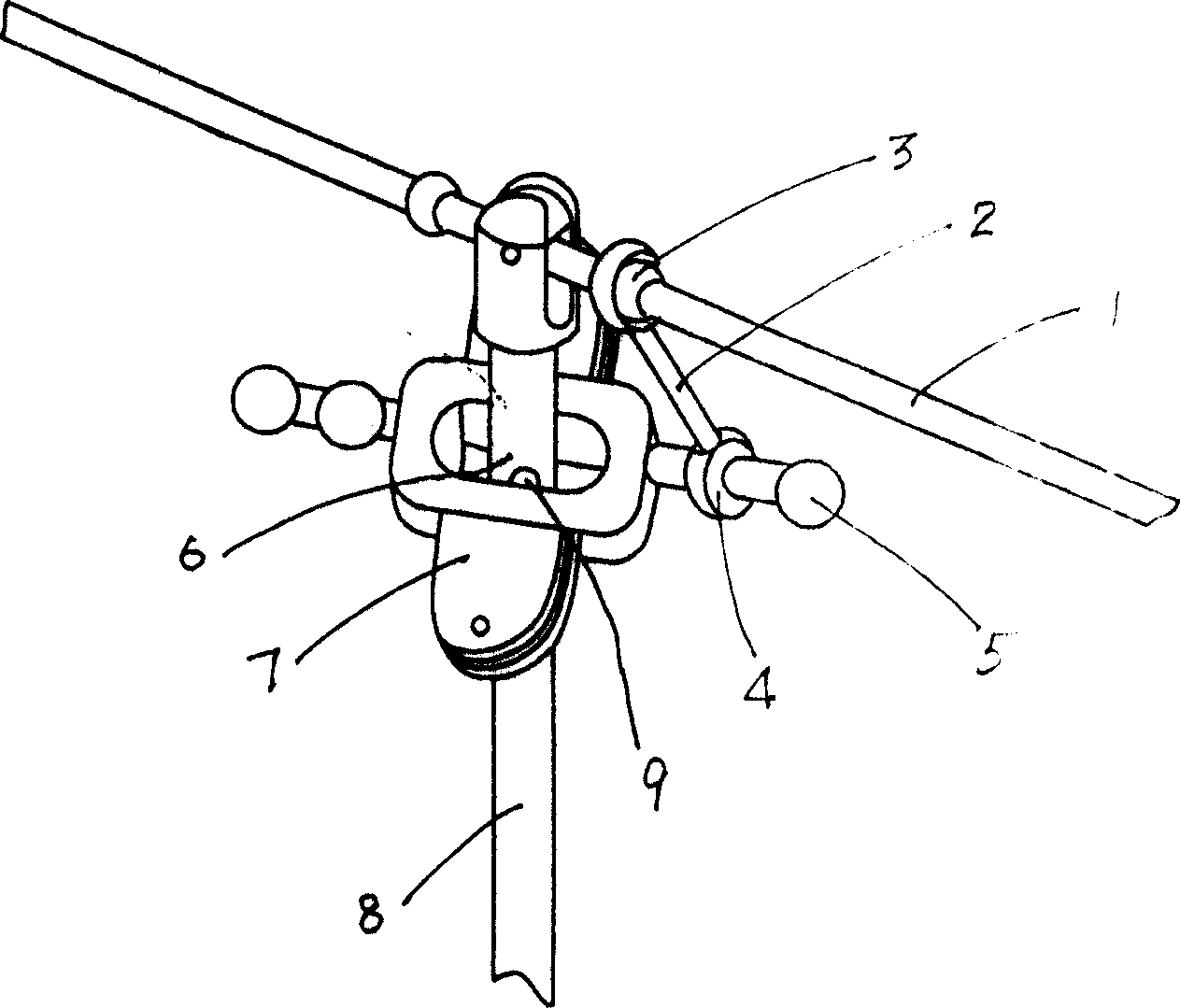
[0010] As shown in the accompanying drawings, a balance mechanism of a remote-controlled coaxial twin-rotor model helicopter comprises a balance bar 1, an upper rotor paddle clip 7, and an upper connecting rod 2; The connecting rod 2 is connected with the rocker ball of the upper rotor blade clamp, and the upper rotor blade clamp 7 is hinged with the sleeve shaft 6 sleeved outside the inner shaft 8 through the hinge shaft 9; it is characterized in that the said upper connecting rod 2 The connected balance bar 1 and upper rotor paddle clamp 7, its connection position can be adjusted; the rocker ball head of said rotor paddle clamp 7 has rocker ball head 1 and rocker ball head 2 two, and the rocker ball head 2 of the balance bar The upper link 1 connected to the arm ball head 3 can be connected with the rocker ball head 1 or the rocker ball head 2, so that the transmission ratio is changed due to the change of the length of the force arm, that is, the stability of the balance sys...


PUM


Abstract

The balance mechanism for remotely controlled coaxial double rotary wing model helicopter can meet the requirements for different users to control the model helicopter in different balance performance, and includes balance rod, upper rotary wing oar jig and upper connecting rod. The balance rod is connected to the rocking arm round head of the upper rotary wing oar jig via the upper connecting rod, and the upper rotary wing oar jig is hinged to the sleeve shaft outside the inner shaft via a hinging axis. The present invention features the adjustable connecting position between the balance rod and the upper rotary wing oar jig, changeable balance force arm length, changeable transmission ratio and changeable stability of the balance mechanism. The present invention makes it possible to select different connection position to reach proper balance performance.

Description

technical field [0001] The invention relates to the technical field of aircraft, in particular to a balance mechanism of a remote-controlled model helicopter. Background technique [0002] The stability of remote control model helicopters is poor, and they have higher requirements for control technology. Compared with those who have mastered certain control skills, beginners have relatively different requirements for the balance performance of remote control model helicopters; beginners mainly The purpose is to fly the remote control model helicopter smoothly and safely, so the model helicopter needs to be well balanced. The sensitivity of the helicopter control system is high. [0003] The balance mechanism of the remote control coaxial double-rotor model helicopter is connected by the balance bar on the top of the model helicopter and the ball head on the balance bar through the upper connecting rod and the rocker arm ball head of the upper rotor blade. When the model hel...

Claims


Application Information

Patent Timeline
Patent Type & Authority Applications(China)
IPC IPC(8): B64C27/82A63H27/133A63H27/20
Inventor 黄国川
Owner 黄国川
Learn More