Eureka AIR delivers breakthrough ideas for toughest innovation challenges, trusted by R&D personnel around the world.

Display device

A display device and a technology for displaying patterns, which are applied to display devices, sports accessories, instruments, etc., can solve the problems of seeing the back side and difficulty in obtaining transparency, etc., and achieve the effect of increasing light incident rate and expanding uses

Inactive Publication Date: 2007-04-18
ORMON CORP
View PDF1 Cites 5 Cited by
  • Summary
  • Abstract
  • Description
  • Claims
  • Application Information

AI Technical Summary

Problems solved by technology

[0004] However, in the above-mentioned display device, the light-emitting part is easy to enter the field of view, and it is difficult to obtain the desired transparency. Therefore, there is a problem that it is difficult to see the back side through the light guide plate.

Method used


Image

  • Display device
  • Display device
  • Display device

Examples


Embodiment

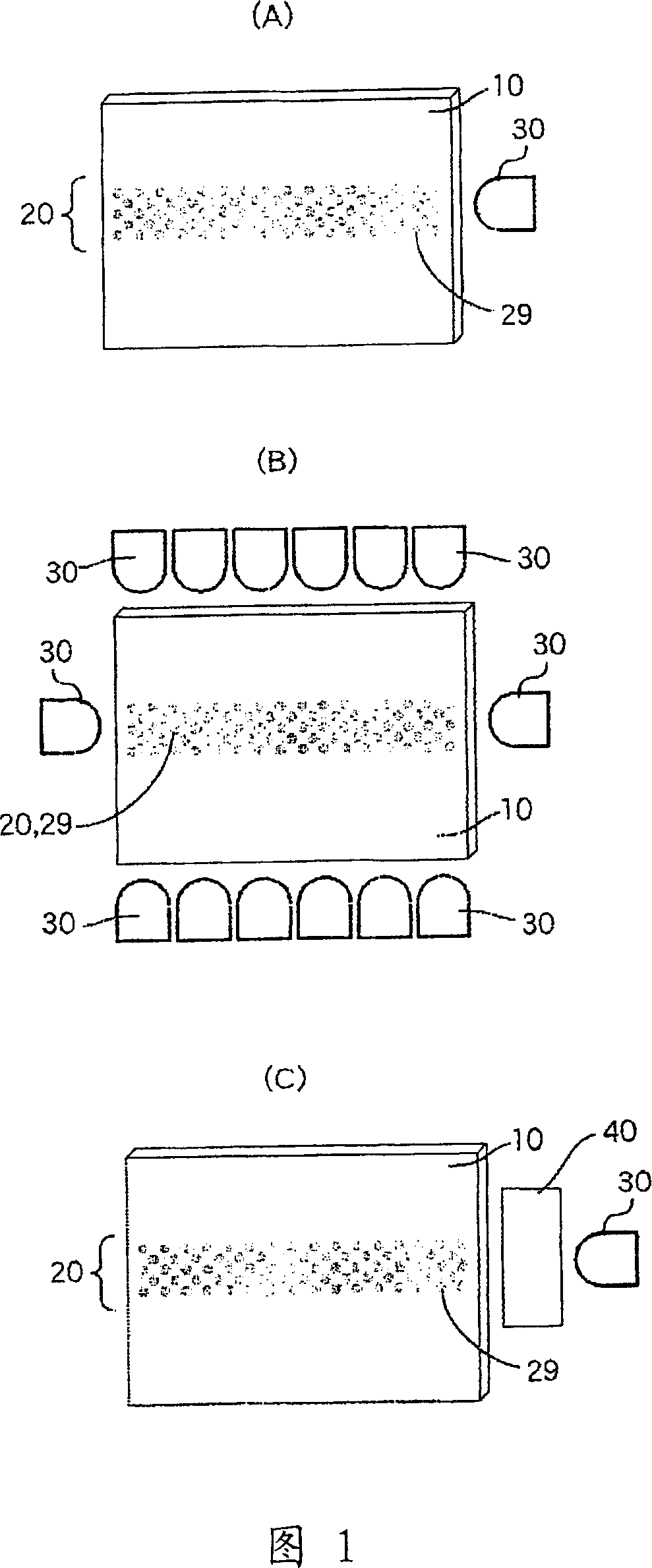
[0053] As shown in FIG. 7 , on one side surface of a transparent polycarbonate resin plate with a width of 100 mm, a length of 150 mm, and a thickness of 2 mm, shallow pits 29 of micro-hemispherical recesses with a diameter of 100 μm are set as islands with a pitch of 200 μm. grid shape to obtain a translucent substrate 10 having a display pattern 20 with a width of 10 mm, a length of 130 mm, and an area density of shallow pits of 10%. Furthermore, on the both side end faces of the translucent substrate 10, two PMMA (polymethyl methacrylate) cylindrical lenses 40 with a focal length of 10.6 mm and a red lens with a diameter of 5.9 mm and a brightness of 7700 mcd (typ.) are arranged respectively. Two LED30 (product name: LUR3333H (manufactured by LIGITEK)) (FIG. 7A).

[0054] Furthermore, when the light-transmitting substrate 10 is visually observed without turning on the LED, the existence of the shallow pits does not obstruct the eyes at all, and the rear side can be fully se...


PUM

PropertyMeasurementUnit
Opening areaaaaaaaaaaa

Abstract

The present invention relates to a display device, which is generally easy to see through the back side, and illuminates a predetermined display pattern to display it as needed. For this purpose, the display pattern (20) is formed by the micro-recesses (29) provided on at least one side of the light-transmitting substrate (10), and at least one light source is arranged on the side end surface of the light-transmitting substrate (10) (30). In addition, the area density of the tiny recesses (29) forming the display pattern (20) is below 20%, and the opening area of ​​one recess (29) is below 0.03mm2.

Description

technical field [0001] The present invention relates to a display device, in particular, which is usually transparent, but is illuminated as needed to display display patterns such as dots, lines, characters, numbers, and patterns. Background technique [0002] Conventionally, as a display device, for example, there is a display device as follows (refer to Patent Document 1), which has: a variable symbol display device capable of variably displaying a plurality of symbols; A permanent light guide plate, and a light source that irradiates light from an end surface inside the light guide plate; it guides the light from the light source into the interior from the end surface of the light guide plate, diffuses through the light emitting portion formed on the surface of the light guide plate, displayed by reflection. [0003] Patent Document 1: (Japanese) Unexamined Patent Publication No. 11-137774 [0004] However, in the above-mentioned display device, since the light-emittin...

Claims


Application Information

Patent Timeline
IPC IPC(8): G09F13/18A63F5/04G09F13/04G09F13/08
CPCG09F13/08G09F13/0409
Inventor 冈安裕长坂昭吾园田真也久保田毅
Owner ORMON CORP
Why Eureka
Eureka Blog
Learn More