Optic element forming device

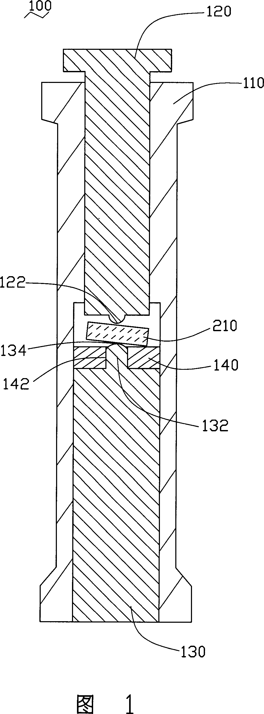
An optical element and molding device technology, which is applied in the optical elements, glass molding, application, etc., can solve the problems of eccentricity of the preform 210 and difficult demolding of the preform 210, etc.

Inactive Publication Date: 2007-04-25
HONG FU JIN PRECISION IND (SHENZHEN) CO LTD +1
View PDF0 Cites 3 Cited by
  • Summary
  • Abstract
  • Description
  • Claims
  • Application Information

AI Technical Summary

Problems solved by technology

[0006] However, since the preform 210 is sometimes placed obliquely on the protrusion 132 and the release member 140, the molding operation may cause an eccentricity of the preform 210.
Moreover, the above-mentioned compression molding process is carried out in a high-temperature and high-pressure environment. During the ejection operation after the lens molding operation is completed, the mold sticking phenomenon often occurs between the preform 210 and the second molding surface 134, that is, the preform 210 is difficult to be formed. Release on the second molding surface 134

Method used


Image

  • Optic element forming device
  • Optic element forming device
  • Optic element forming device

Examples


Embodiment Construction

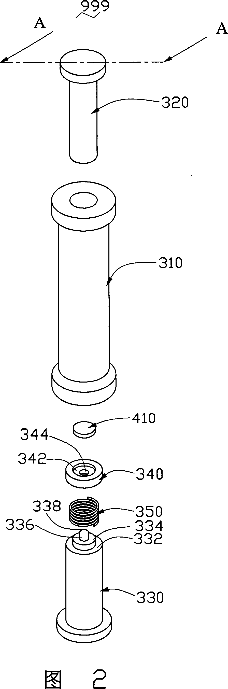
[0014] As shown in FIG. 2 , it is a lens forming device 999 disclosed in a preferred embodiment of the present invention. The lens forming device 999 is used to perform lens forming operation on a preform 410, which includes: a sleeve 310, a first mold core 320, a second mold core 330, a demoulding part 340 and an elastic part 350 . The sleeve 310 accommodates the first mold core 320, the second mold core 330, the demoulding part 340 and an elastic part 350 therein, and guides the first mold core 320 to open / close relative to the second mold core 330 model movement. The cooperation between the first mold core 320 and the second mold core 330 can define the shape of the lens that the preform 410 needs to be molded. The demoulding part 340 is placed on the elastic part 350 to carry the preform part 410 . The elastic member 350 is placed on the second mold core 330 to elastically support the release member 340 .

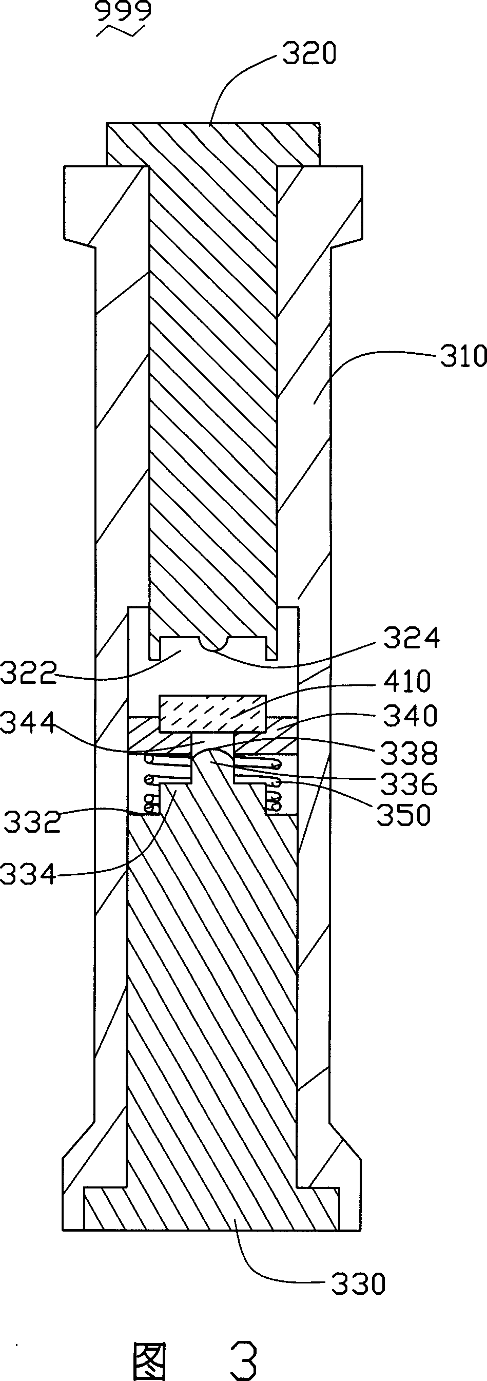
[0015] As shown in FIG. 3 , the first mold core 320 has a groo...


PUM


Abstract

The invention discloses an optical element moulding device, which comprises the following parts: first mould core, second mould core, stripping component and elastic element, wherein the first mould core mates the second mould core as optical element shape; the stripping component bears the pre-shaping piece; the elastic element lies between stripping piece and second mould core, which bears the stripping piece on the second mould core elastically.

Description

【Technical field】 [0001] The invention relates to an optical element forming device, in particular to a lens forming device. 【Background technique】 [0002] Due to the rapid development of CD players, digital cameras and video cameras, the application of optical components is becoming more and more extensive. How to improve the manufacturing technology of optical components has become a concern of the industry. [0003] At present, the manufacturing methods of optical components mainly include injection molding and compression molding. The injection molding method is mainly suitable for the manufacture of optical components made of plastic, and the compression molding method is mainly suitable for the manufacture of optical components made of glass. Among them, the compression molding method mainly uses a compression molding device to pressurize the blank to form a lens of a desired shape. [0004] FIG. 1 shows a lens forming device 100 disclosed in the prior art, which u...

Claims


Application Information

Patent Timeline
Patent Type & Authority Applications(China)
IPC IPC(8): C03B11/08B29C43/50B29L11/00
CPCC03B2215/06C03B2215/61B29L2011/0016B29C2043/3618B29C2043/3255B29C43/361B29C2043/5841B29D11/00413C03B2215/49B29C43/021B29C2043/3652C03B2215/72C03B11/08
Inventor 江宗韦
Owner HONG FU JIN PRECISION IND (SHENZHEN) CO LTD
Why Eureka
Try Eureka