Mining plow

A recovery planer and planer technology, which is applied in the direction of slitting machinery, earthwork drilling and mining, etc., can solve the problems of time-consuming

Active Publication Date: 2007-04-25
CATERPILLAR INC
View PDF1 Cites 5 Cited by
  • Summary
  • Abstract
  • Description
  • Claims
  • Application Information

AI Technical Summary

Problems solved by technology

However, changing the tool holder at the point of use, for example in the underground working face, is

Method used


Image

  • Mining plow
  • Mining plow

Examples


Embodiment Construction

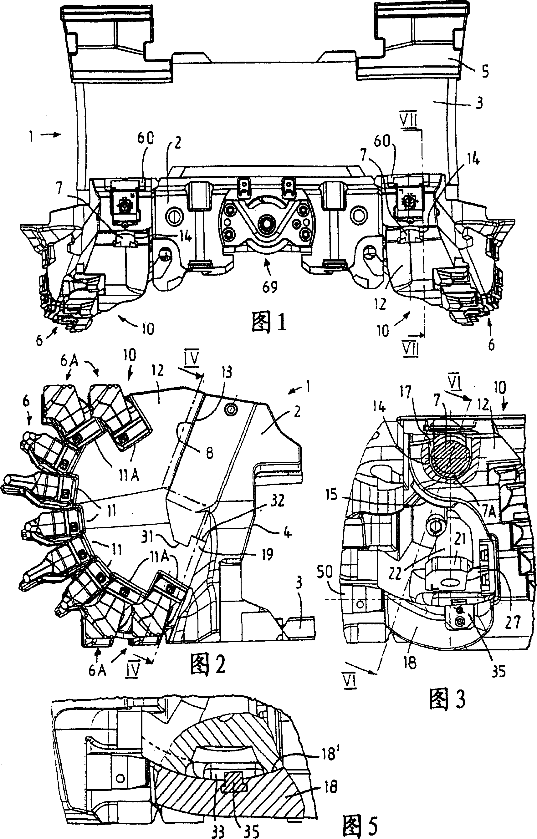
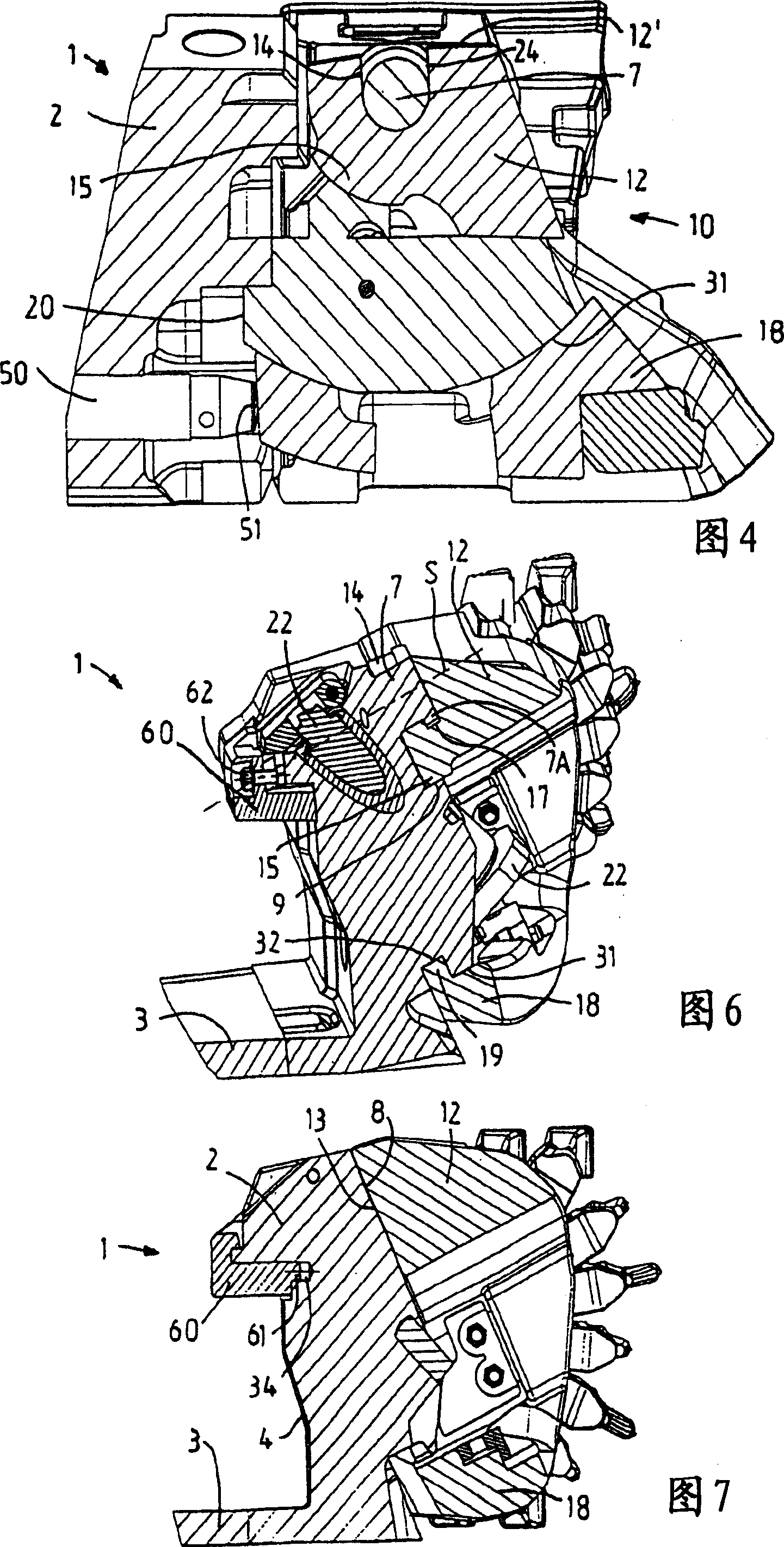
[0021] The recovery planing mechanism indicated generally by 1 in the figures is an embodiment of a tow hook planer and has a planer base body 2 designed as a casting, to which a multi-part planer support plate (Hobelschwert ) planer support plate part 3 in the center. The filling-side back 4 of the planer base body 2 is designed such that the planer 1 can be guided by its planer base body 2 in a supported manner on a guide plate on the working surface side of a further conveyor, not shown. At the same time the recovery planer engages with its planer strut 3 the two feed lines of the conveyor from below, and a guide lug 5 on the filling-side end of the planer strut 3 engages a planer for moving the planer 1 In the chain guide channel of the traction chain of the machine, in order to use the recovery planer 1 to mine coal in the working face in the underground, a tool holder 10 is fixed on the planer base 2 to swing for each moving direction of the recovery planer 1, and two of...


PUM


Abstract

The invention relates to a recovery planer comprising a planer base (2) guided on a conveyor, which has a pivot pin on an inclined support surface (8) for any direction of movement of the planer (7) a swingable support for a knife rest (10), and includes two knife rests (10), each knife rest is supported swingably on the corresponding swing pin (7) by means of a swing support and has A base (18), by means of which the base tool holder (10) is guided on a pivoting surface (31) formed on the planer base below the bearing surface and oriented concentrically to the axis of rotation of the associated pivoting pin (7) . According to the invention, the swivel support of the tool holder (10) is formed as a groove (14) with open edges, by means of which the tool holder (10) can be pushed parallel to the support surface (8) onto the swivel pin (7) in a mounting swivel position. superior. Mounting of each tool holder can then be carried out relatively simply from below.

Description

technical field [0001] The invention relates to a recovery planer, in particular for coal mining, comprising a planer base guided on a movable conveyor, the planer base having an inclined support surface for any direction of movement of the planer. A swing pin for swingably supporting the knife holder; A guide is formed on the pivot surface below the support surface on the planer base body, oriented concentrically to the axis of rotation of the associated pivot pin. Background technique [0002] The same recovery planer is known from DE 201 18 259 U1 as an embodiment of a tow hook planer. Owing to the change of the swinging direction and the support of the tool holder on the base body using the inclined bearing surface, the force introduced into a connecting rod can be reduced compared with the prior art, via which the two tool holders are connected to each other. Their oscillating movements are kinematically connected to one another. At the same time, the force direction...

Claims


Application Information

Patent Timeline
IPC IPC(8): E21C27/32
CPCE21C27/32E21C35/18
Inventor A·克莱比施G·西彭科特K·杜恩克N·黑塞D·贝特尔曼
Owner CATERPILLAR INC
Why Eureka
Try Eureka