Mining plow

A recovery planer and planer technology, which is applied in the direction of slitting machinery, earthwork drilling and mining, etc., can solve the problems of time-consuming

Active Publication Date: 2011-10-05
CATERPILLAR INC
View PDF1 Cites 0 Cited by
  • Summary
  • Abstract
  • Description
  • Claims
  • Application Information

AI Technical Summary

Problems solved by technology

However, changing the tool holder at the point of use, for example in the underground working face, is still time-consuming and often difficult due to the small seam thickness in this same recovery planer.

Method used


Image

  • Mining plow
  • Mining plow
  • Mining plow

Examples


Embodiment Construction

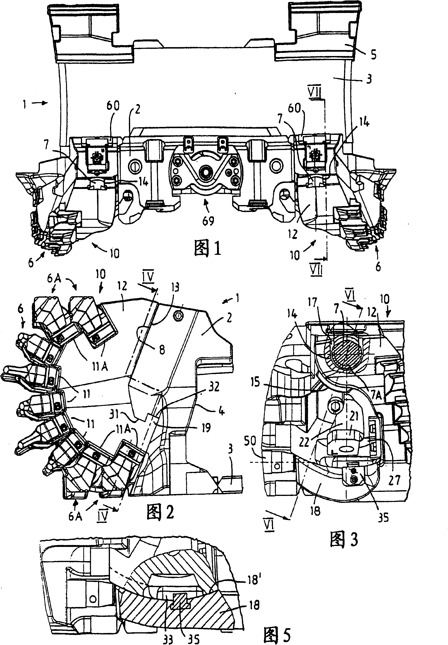
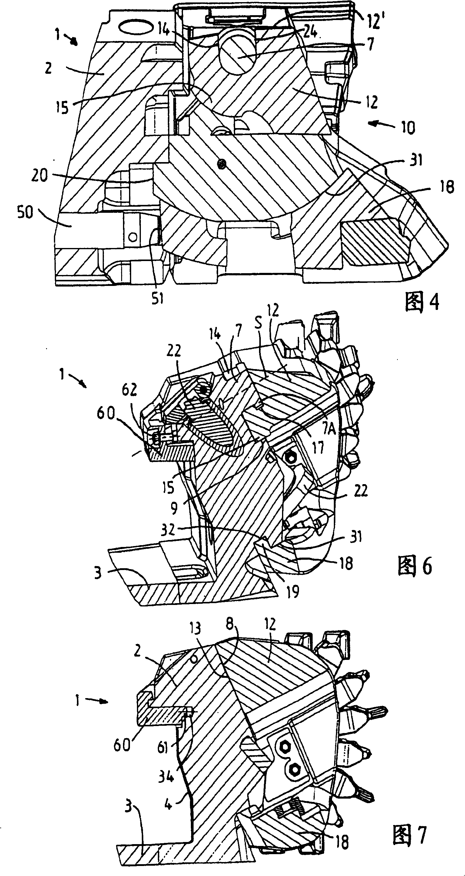
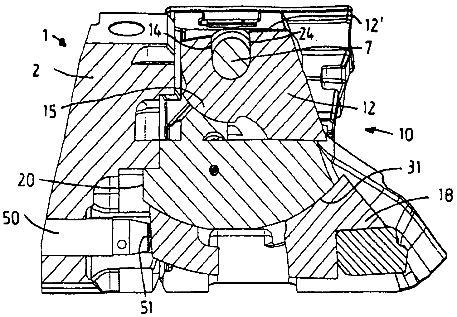
[0021] The planing mechanism, which is generally marked by the reference 1 in each figure, becomes the implementation form of the tow-hook planer and has a planer base body 2 formed as a casting, on which a multi-piece planer support plate is rigidly fixed. ) The planer support plate in the center. The back side 4 of the filling side of the planer base body 2 is configured so that the planer base body 2 can be guided by its planer base body 2 on a guide plate on the working surface side of another conveyor, not shown. At the same time, the planer uses its planer support plate 3 to embed the two branches of the conveyor from below, and a guide ear 5 on the end of the filling side of the planer support plate 3 is embedded with a planer for moving the planer 1 In the chain guide channel of the machine traction chain, in order to use the mining planer 1 to excavate coal in the underground working face, a tool holder 10 is swingably fixed on the planer base 2 for each movement direc...


PUM


Abstract

A mining plow with a plow basic body which can be guided on a conveyor and which has on an inclined bearing surface a pivoting bolt for the pivotable mounting of a cutter carrier for each plow travel direction Two cutter carriers are mounted pivotably on respective pivoting bolts by a pivot bearing such that each cutter carrier is guided on a pivoting surface oriented concentrically about the pivot axis of the associated pivoting bolt and formed below the bearing surface on the plow basic body. The pivot bearing of each cutter carrier includes an open-edged receptacle, each cutter carrier being located on the pivoting bolt parallel to the bearing surface in a pivoting mounting position.

Description

Technical field [0001] The present invention relates to a mining planer, particularly for coal mining, which includes a planer base that can be guided on a movable conveyor. The planer base has an inclined supporting surface for any direction of movement of the planer. A swing pin for swingably supporting the tool holder; and includes two tool holders, which are swingably supported on the corresponding swing pin by means of a swing support and have a bottom, by means of which the tool holder is corresponding to A guide on a pivot surface formed on the base body of the planer below the bearing surface, which is oriented concentrically to the axis of rotation of the associated pivot pin. Background technique [0002] From DE 201 18 259 U1, the same type of mining planer is known as a Schwerthobel implementation. Due to the use of the inclined supporting surface for the change of the swing direction of the tool holder and the support of the tool holder on the base, compared with th...

Claims


Application Information

Patent Timeline
Patent Type & Authority Patents(China)
IPC IPC(8): E21C27/32
CPCE21C27/32E21C35/18
Inventor A·克莱比施G·西彭科特K·杜恩克N·黑塞D·贝特尔曼
Owner CATERPILLAR INC
Why Eureka
Try Eureka