Electronically compensated LCD assembly

一种组件、电压的技术,应用在偏振补偿领域,能够解决不精确延迟补偿、降低高对比度成像器面板生产量等问题

Inactive Publication Date: 2007-04-25
JDS UNIPHASE CORP
View PDF5 Cites 6 Cited by
  • Summary
  • Abstract
  • Description
  • Claims
  • Application Information

AI Technical Summary

Problems solved by technology

However, due to variations in the residual IPR of the individual LCoS panels from the wafer, this approach will result in imprecise delay compensation for at least some imager components and will reduce the production yield of high-contrast imager panels

Method used


Image

  • Electronically compensated LCD assembly
  • Electronically compensated LCD assembly
  • Electronically compensated LCD assembly

Examples


Embodiment Construction

[0076] Definition of Terms

[0077] [72] In relation to light polarizing, compensating and retarding layers, films or plates described in this application, the following definitions are given for the terms used throughout this application.

[0078] [73] The term "optical axis", when referring to a birefringent material such as a liquid crystal (LC), is used to denote an axis in the material whereby light rays propagating along the axis are not birefringent. Hereafter in the specification, LC materials used in LCD panels are assumed to be uniaxial and have positive birefringence, i.e. extraordinary refractive index n e is the highest index of refraction for the material where the optical axis coincides with the extraordinary axis.

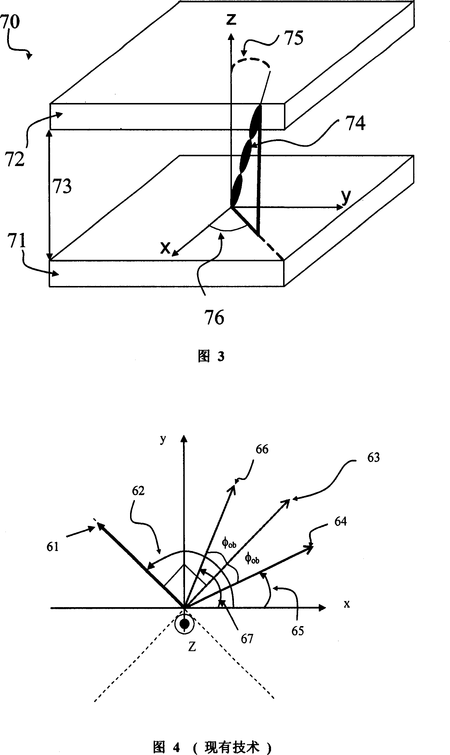
[0079] [74] The term "slow axis (SA)" as used herein means the projection of the optical axis of a birefringent film (or plate, or layer) onto the plane of the film.

[0080] [75] The term "tilted structure" or "tilted orientation" means that the ...


PUM


Abstract

The invention relates to a method of electronic contrast enhancement for an LCD panel for use in an imaging device. The method comprises the step of coupling the LCD panel with a trim retarder in a pre-determined azimuthal orientation for at least partially compensating the residual in-plane retardance, followed by the step of non-mechanical fine-tuning of a dark state of the LCD panel. In the preferred embodiment, the fine-tuning of the dark state of the LCD panel is realized by adjusting the dark-state magnitude of the LC voltage. The method can be used in batch, e.g. wafer-level manufacturing of integrated trim retarder / LCD panels assemblies that can be electronically tuned to provide high on / off contrast.

Description

[0001] Cross References to Related Applications [0002] [01] This application claims priority to US Provisional Application 60 / 727,969, filed October 18, 2005, entitled "Electrically Compensated LCD Assembly," which is hereby incorporated by reference into this application. This application is related to U.S. Patent Application No. 11 / 009,476 filed on December 10, 2004, U.S. Patent Application No. 11 / 358,605 filed on February 21, 2006, and U.S. Patent Application No. 11 / 358,605 filed on May 23, 2006. 419,872 is related to US Patent Application 11 / 468,860 filed August 31, 2006, all of which are hereby incorporated by reference into this application. technical field [0003] [02] This application relates generally to polarization compensation for projection displays, and in particular to electrically tunable LCD assemblies incorporating LCD panels and trim retarders, and to methods for electrically tuning said LCD assemblies to enhance contrast. Background of the invention ...

Claims


Application Information

Patent Timeline
Patent Type & Authority Applications(China)
IPC IPC(8): G02F1/13G02F1/1333
CPCG03B21/2073G03B21/20G02F1/13363H04N9/3155H04N9/3105H04N9/3197H04N9/3182G02F2413/01H04N9/3152G02F1/133382G02F1/1309G02F1/136277H04N9/3167
Inventor 谭金龙安德鲁·托马斯·泰勒阿普巴·普拉德汉
Owner JDS UNIPHASE CORP
Why Eureka
Try Eureka