Power supply unit
A technology of power supply device and DC power supply, which is used in circuits, output power conversion devices, electrical components, etc.
- Summary
- Abstract
- Description
- Claims
- Application Information
AI Technical Summary
Problems solved by technology
Method used
Image

Examples
no. 1 example
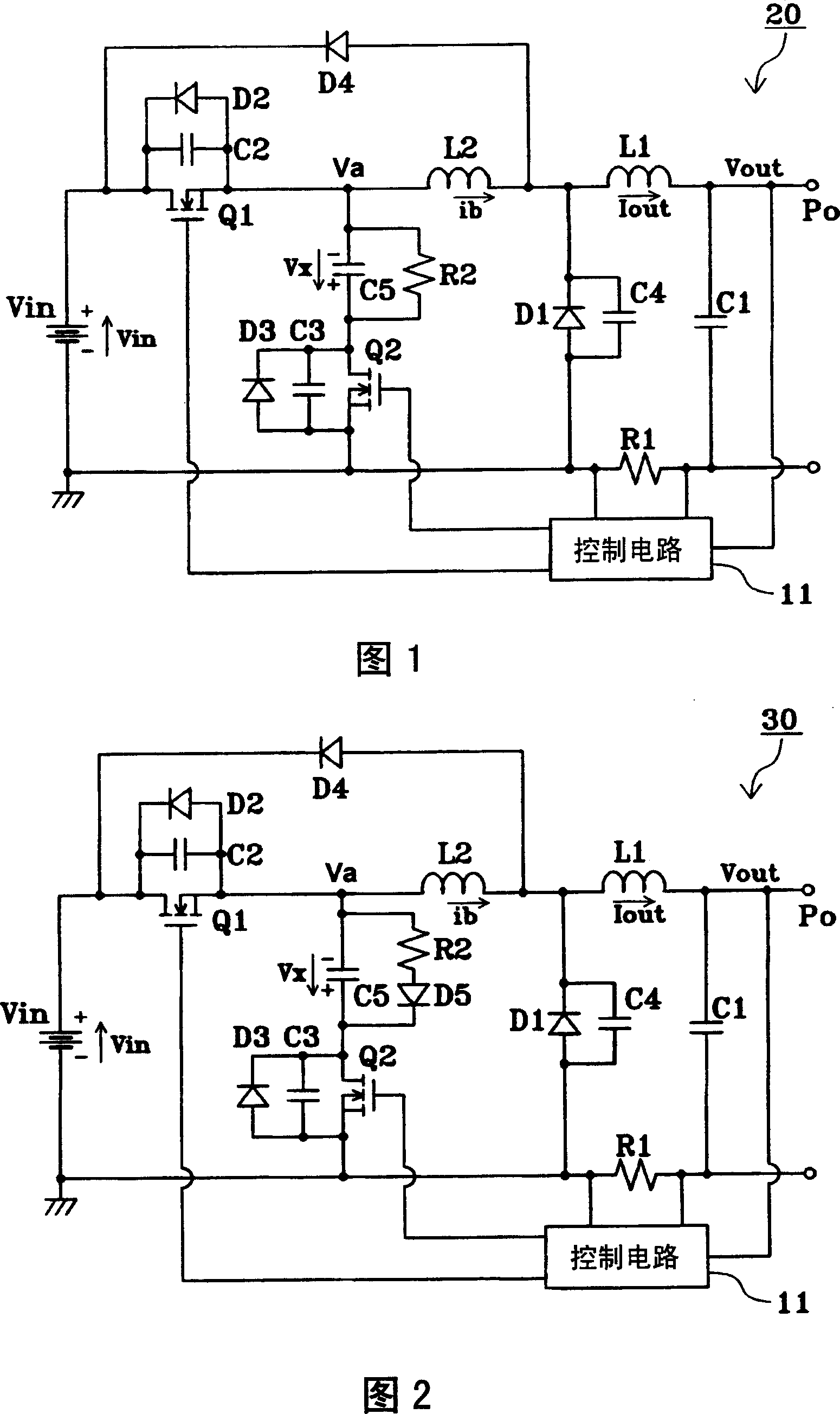
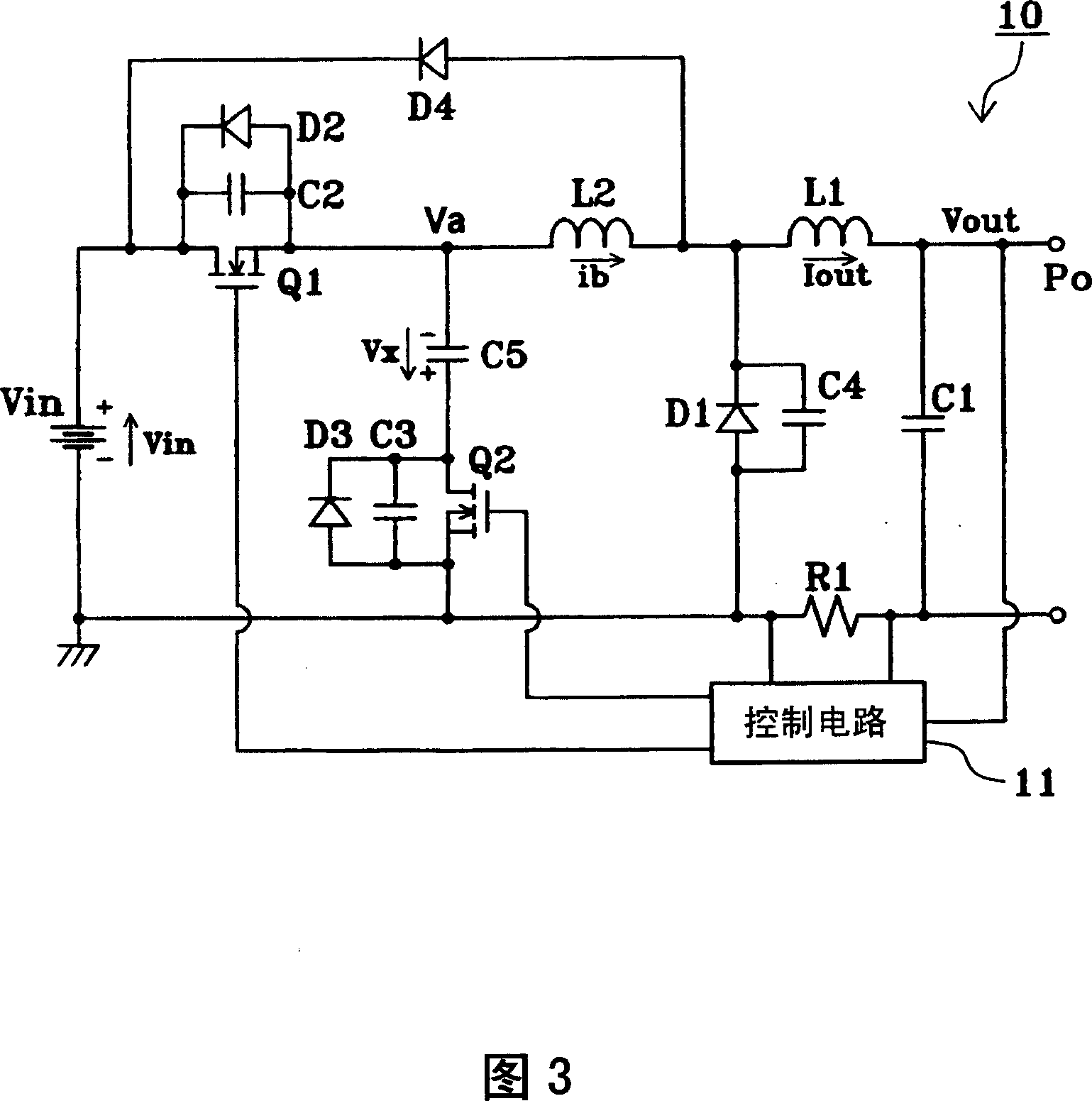
[0049] Fig. 1 is a circuit diagram of a power supply unit according to a first embodiment of the present invention. In FIG. 1, the same reference numerals are used to designate the same or similar elements as those in FIG. 3, and their descriptions are omitted.
[0050] In the power supply device shown in FIG. 1 , the resistor R2 as the first resistor is connected in parallel to the capacitor C5 as the first capacitor, and the first capacitor is also provided in the power supply device 10 of FIG. 3 . The rest of the structure is the same as that of the power supply device 10 . In this embodiment, the resistance value of the resistor R2 is set to 2.4 kΩ.
[0051] In the power supply unit 20 having the above structure, even when trying to charge the capacitor C5 in the reverse direction of normal operation when the load is light, since the charge is discharged through the resistor R2, the charging of the capacitor C5 in the reverse direction can be ignored. Thereby, generation...
no. 2 example
[0057] Fig. 2 is a circuit diagram of a power supply unit according to a second embodiment of the present invention. In FIG. 2, the same or similar elements as those in FIG. 1 are denoted by the same reference numerals, and their descriptions are omitted.
[0058] In the power supply unit 30 shown in FIG. 2 , a diode D5 connected in series with the resistor R2 as the first resistor is provided as a fourth diode, and the first resistor is also provided in the power supply unit 20 of FIG. 1 . That is, a series circuit including a resistor R2 and a diode D5 is connected in parallel with a capacitor C5. Diode D5 is arranged such that its cathode is connected to MOSFET Q2. The rest of the structure is the same as that of the power supply device 20 .
[0059] In the power supply device 30 having the above structure, even if an attempt is made to charge the capacitor C5 in the reverse direction at start-up, since the charge is discharged through the resistor R2 and the diode D5, th...
PUM
 Abstract
Description
Claims
Application Information
 - R&D
- Intellectual Property
- Life Sciences
- Materials
- Tech Scout
- Unparalleled Data Quality
- Higher Quality Content
- 60% Fewer Hallucinations
Browse by: Latest US Patents, China's latest patents, Technical Efficacy Thesaurus, Application Domain, Technology Topic, Popular Technical Reports.
© 2025 PatSnap. All rights reserved.Legal|Privacy policy|Modern Slavery Act Transparency Statement|Sitemap|About US| Contact US: help@patsnap.com