
Control circuit and control method

A technology of control circuit and control method, applied in control/regulation systems, electrical components, regulating electrical variables, etc., and can solve problems such as high power loss

Active Publication Date: 2014-09-03
SYST GEN +1
View PDF8 Cites 4 Cited by
  • Summary
  • Abstract
  • Description
  • Claims
  • Application Information

AI Technical Summary

Problems solved by technology

[0002] Existing active clamping circuits can only achieve ZVS under certain load conditions
Also, high circulating currents during light loads lead to higher power loss issues

Method used


Image

  • Control circuit and control method
  • Control circuit and control method
  • Control circuit and control method

Examples


Embodiment Construction

[0105] In order to make the above-mentioned objects, features and advantages of the present invention more comprehensible, a preferred embodiment will be described in detail below together with the accompanying drawings.

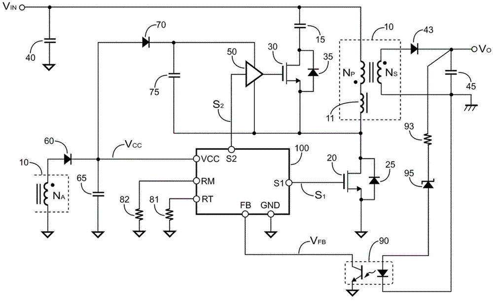
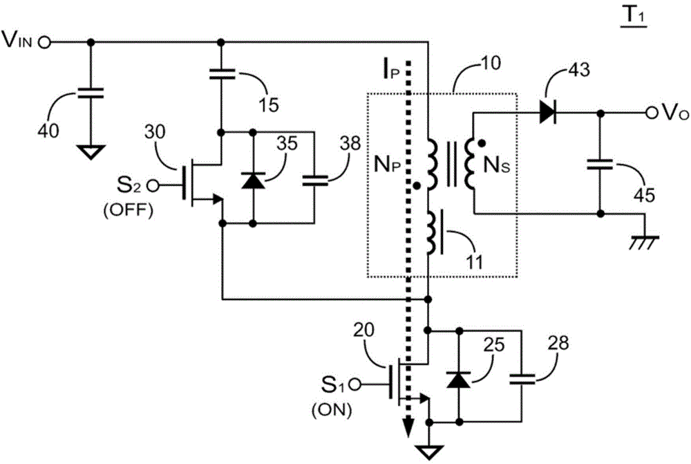
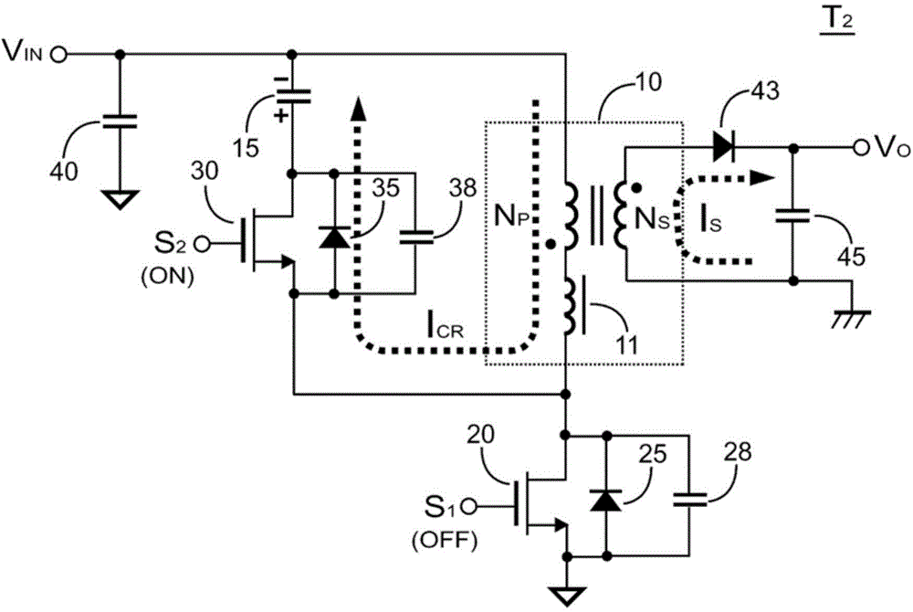
[0106] figure 1 A flyback power converter according to an embodiment of the present invention is shown. Transformer 10 receives the input voltage V of the power converter IN . Transistor (also referred to as “low-side transistor”) 20 is coupled to switch primary side winding N of transformer 10 P . The controller 100 generates a switching signal S at its terminal S1 1 , while the switching signal S 1 used to drive transistor 20 to adjust the output voltage of the power converter V O . switch signal S 1 is based on the feedback signal V at the terminal FB of the controller 100 FB And generated. Feedback signal V FB with the output voltage of the power converter V O Associated. The secondary side winding N of the transformer 10 S The output volta...


PUM


Abstract

The invention provides a control circuit and a control method. The control method is used for controlling an active-clamp flyback power converter. The control method comprises the steps of generating a switching signal according to a feedback signal to switch a low voltage side transistor and regulate the output of the active-clamp flyback power converter; generating an active-clamp signal after the switching signal is forbidden; generating lag bias voltage to regulate the feedback signal; periodically generating a pulse signal to start the switching signal, wherein the low voltage side transistor is used for switching a transformer; the switching signal is used for driving the low voltage side transistor; the active-clamp signal is used for driving a high voltage side transistor; the pulse width of the active-clamp signal is determined by a first resistor; the high voltage side transistor is connected with a capacitor in series to form an active-clamp circuit; in the state of heavy load, the minimum frequency of the switching signal is determined by a second resistor.

Description

technical field [0001] The invention relates to an active clamping flyback power converter, in particular to a control circuit for the active clamping flyback power converter. Background technique [0002] Existing active clamping circuits can only achieve ZVS under certain load conditions. Furthermore, high circulating currents during light loads lead to higher power loss issues. Related techniques can be found in US Patent No. 5,570,278 entitled "Clamped Continuous Flyback Power Converter", US Patent No. 6,069,803 entitled "Offset Resonance Zero Voltage Switching Flyback Converter" and "Active-clamp Circuit for Quasi -resonant Flyback Power Converter Power Converter" and number 20110305048 US patent application. Contents of the invention [0003] Therefore, the present invention proposes a control circuit for actively clamping a flyback power converter. It achieves zero voltage switching at heavy loads and high efficiency at light loads. The purpose of the present in...

Claims


Application Information

Patent Timeline
IPC IPC(8): H02M3/335
Inventor 杨大勇刘晏铭
Owner SYST GEN
Learn More