Automatic cleaning device in dust collection tube of vacuum cleaner

A technology for automatic cleaning and dust collection, which can be used in suction filters and other directions to solve problems such as clogging of foreign substances such as dust.

Inactive Publication Date: 2007-05-02
LG ELECTRONICS (TIANJIN) APPLIANCES CO LTD
View PDF0 Cites 15 Cited by
  • Summary
  • Abstract
  • Description
  • Claims
  • Application Information

AI Technical Summary

Problems solved by technology

[0013] The purpose of the present invention is to solve the problem of dust and other foreign substances blocking the filter holes of the filter tank in the dust collection tube in the prior art, a

Method used


Image

  • Automatic cleaning device in dust collection tube of vacuum cleaner
  • Automatic cleaning device in dust collection tube of vacuum cleaner

Examples


Embodiment Construction

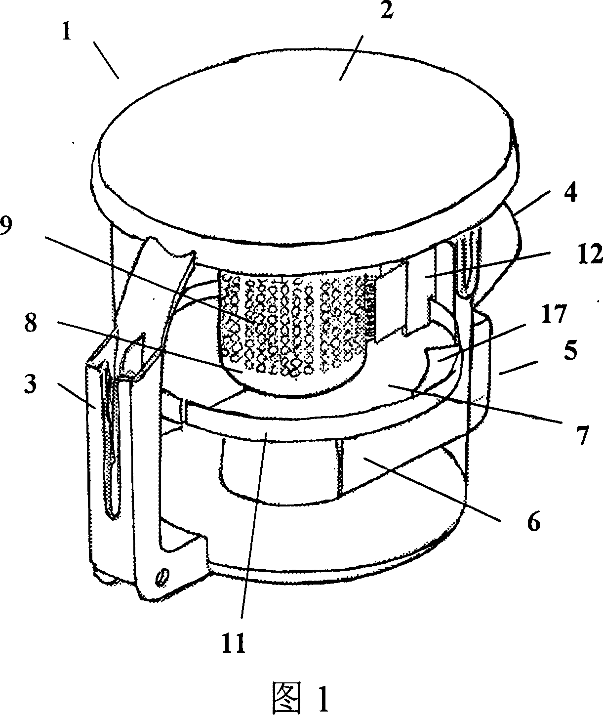
[0028] The present invention will be described in detail below in conjunction with the accompanying drawings and embodiments.

[0029] An automatic cleaning device for the interior of a dust collection cylinder of a vacuum cleaner, comprising a handle 3 formed on one side of the dust collection cylinder, a hinged and openable cylinder cover 2 at the top of the dust collection cylinder 1, which is divided into an upper part and a lower part by a horizontal arrangement inside the cylinder And the dividing plate 7 of through hole (not shown) is formed in the center, the filter tank 8 that the bottom mouth runs through is installed on the through hole of dividing plate 7 tops, and the outer wall of dust collection tube 1 top is formed to communicate with the inside of the tube, and its center line is in line with the tube. The air inlet 4 that is tangent to the inner peripheral wall of the cylinder; the air outlet channel 6 communicated with the air outlet on the outer wall of the ...


PUM


Abstract

An automatic cleaning unit in the dust collecting drum of cleaner is composed of an openable cover hinged to the top of dust collecting drum and with an upper ring track on its bottom surface, a perforated isolating plate with a lower ring track on it and an air outlet channel, and a gang brush between said upper and lower ring tracks and revolving along them to remove the dust deposit from the inner surface of dust collecting drum.

Description

technical field [0001] The invention relates to a device for cleaning a filter tank of a vacuum cleaner, in particular to an automatic cleaning device for the inside of a dust collection cylinder of a vacuum cleaner. Background technique [0002] Vacuum suction is a cleaning and sanitary appliance used to remove dust from floors, carpets, walls, furniture, clothing and various gaps. [0003] Vacuum cleaners generally include a vacuum cleaner motor that generates suction from an imported power supply, a motor inlet that forms an air path system, a suction nozzle, a hose, and a dust collection device that collects inhaled matter. [0004] According to the shape of vacuum cleaners, they can be divided into upright vacuum cleaners, horizontal vacuum cleaners and portable vacuum cleaners. [0005] Generally speaking, the upright vacuum cleaner includes a front cover, a rear cover and a bottom case. The top of the front cover is equipped with a vacuum hose connection device, the...

Claims


Application Information

Patent Timeline
IPC IPC(8): A47L9/16
Inventor 李艳君
Owner LG ELECTRONICS (TIANJIN) APPLIANCES CO LTD
Why Eureka
Try Eureka